Measurement device capable of calibrating corner signal and three-dimensional vibration of crankshaft
A crankshaft angle signal, three-dimensional vibration technology, applied in measuring devices, vibration testing, testing of machine/structural components, etc., can solve problems such as inability to determine bending vibration, limited number of gear teeth, low torsional vibration testing accuracy, etc.
Inactive Publication Date: 2011-01-05
TIANJIN UNIV
View PDF1 Cites 0 Cited by
- Summary
- Abstract
- Description
- Claims
- Application Information
AI Technical Summary
Problems solved by technology
However, the main defect of this measurement method is that the number of gear teeth is limited, resulting in low accuracy of the torsional vibration test. At the same time, the measured bending vibration is measured in a fixed coordinate system that is consistent with the overall coordinates of the engine, and the coordinate system that rotates with the crankshaft cannot be determined. bending vibration under
Method used
View moreImage
Smart ImageViewing Examples
Examples
Embodiment Construction
Login to View More PUM
 Abstract
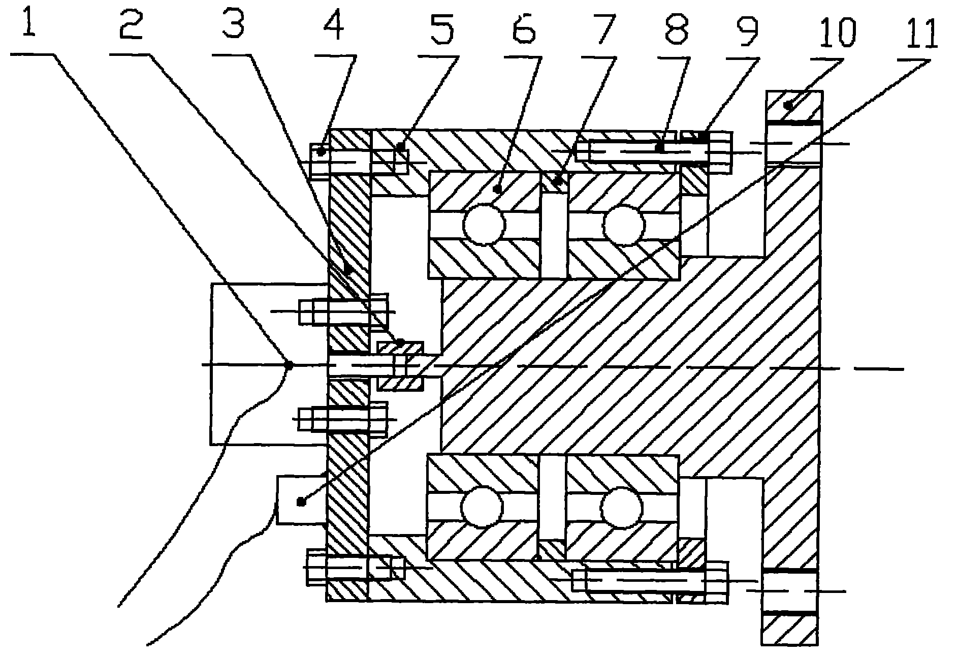
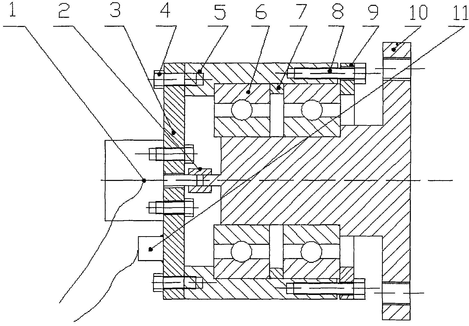
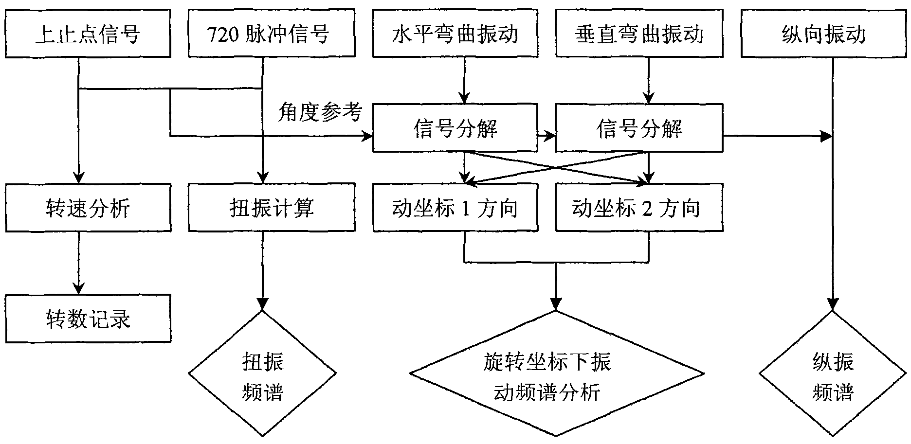
The invention discloses a crankshaft three-dimensional vibration measurement device capable of calibrating a crankshaft corner signal. A photoelectric encoder is fixed in the center hole of a stop block by a bolt, and the stop block is also fastened on the end face of a casing by the bolt. A pair of ball bearings is arranged between the casing and a transmission shaft, and the exterior ends of theball bearings are fixed on the casing by a fastener bolt and a fastening check ring. The exterior end of the stop block is provided with a three-dimensional vibration sensor. The photoelectric encoder is connected with the transmission shaft by a connecting shaft to rotate synchronously and outputs two voltage signals which are respectively used for carrying out the torsional vibration analysis and the top dead centre calibration of a crankshaft. In the invention, bending vibration under different corners of the crankshaft can be decomposed, and synthesis is carried out on the rotating coordinate system of the crankshaft at a position corresponding to the corner of the crankshaft, so that the measurement of the rotating coordinate system of the crankshaft can be realized, bending vibration consistent to the rotating coordinates of the crankshaft is obtained by software calculation, and real-time monitoring can be carried out on an engine in terms of the revolution speed and the revolution number.
Description
Measuring device that can calibrate crankshaft rotation angle signal and three-dimensional vibration of crankshaft technical field The invention belongs to the vibration testing technology of an internal combustion engine, and in particular relates to a technology and a device for three-dimensional vibration measurement of a crankshaft and calibration of the crankshaft rotation angle position. Background technique The crankshaft of an internal combustion engine must bear the effects of gas pressure, torsional moment, bending force, and inertial force at the same time, and aggregate the torque on each crank throw to drive other mechanical rotations to do work. Due to the structural characteristics of the crankshaft, the crankshaft vibration is basically a combination of torsional vibration, bending vibration and longitudinal vibration. The coupling between the crankshaft and the main bearing on the body will cause the body to vibrate and radiate noise. Therefore, the shaft...
Claims
Login to View More Application Information
Patent Timeline
 Patent Type & Authority Patents(China)
IPC IPC(8): G01M15/04G01M7/02
Inventor 梁兴雨舒歌群马维忍董立辉卫海桥
Owner TIANJIN UNIV
Features
- R&D
- Intellectual Property
- Life Sciences
- Materials
- Tech Scout
- Unparalleled Data Quality
- Higher Quality Content
- 60% Fewer Hallucinations
Learn More Browse by: Latest US Patents, China's latest patents, Technical Efficacy Thesaurus, Application Domain, Technology Topic, Popular Technical Reports.
© 2025 PatSnap. All rights reserved.Legal|Privacy policy|Modern Slavery Act Transparency Statement|Sitemap|About US| Contact US: help@patsnap.com


