
Valve used in shifting devices of engineering automobiles

A technology for shifting devices and engineering vehicles, which is applied in the direction of transmission control, components with teeth, belts/chains/gears, etc. It can solve problems such as large volume, complex structure, and high probability of failure, so as to improve reliability Sexuality, compact structure, ensure normal effect

Inactive Publication Date: 2009-11-18
XIAN AEROSPACE YUANZHENG FLUID CONTROL
View PDF0 Cites 2 Cited by
  • Summary
  • Abstract
  • Description
  • Claims
  • Application Information

AI Technical Summary

Problems solved by technology

[0003] The purpose of the present invention is to provide a valve used in the shifting device of engineering vehicles to overcome the technical defects of large volume and complex structure, and a high probability of failure during use.

Method used


Image

  • Valve used in shifting devices of engineering automobiles
  • Valve used in shifting devices of engineering automobiles

Examples


Embodiment Construction

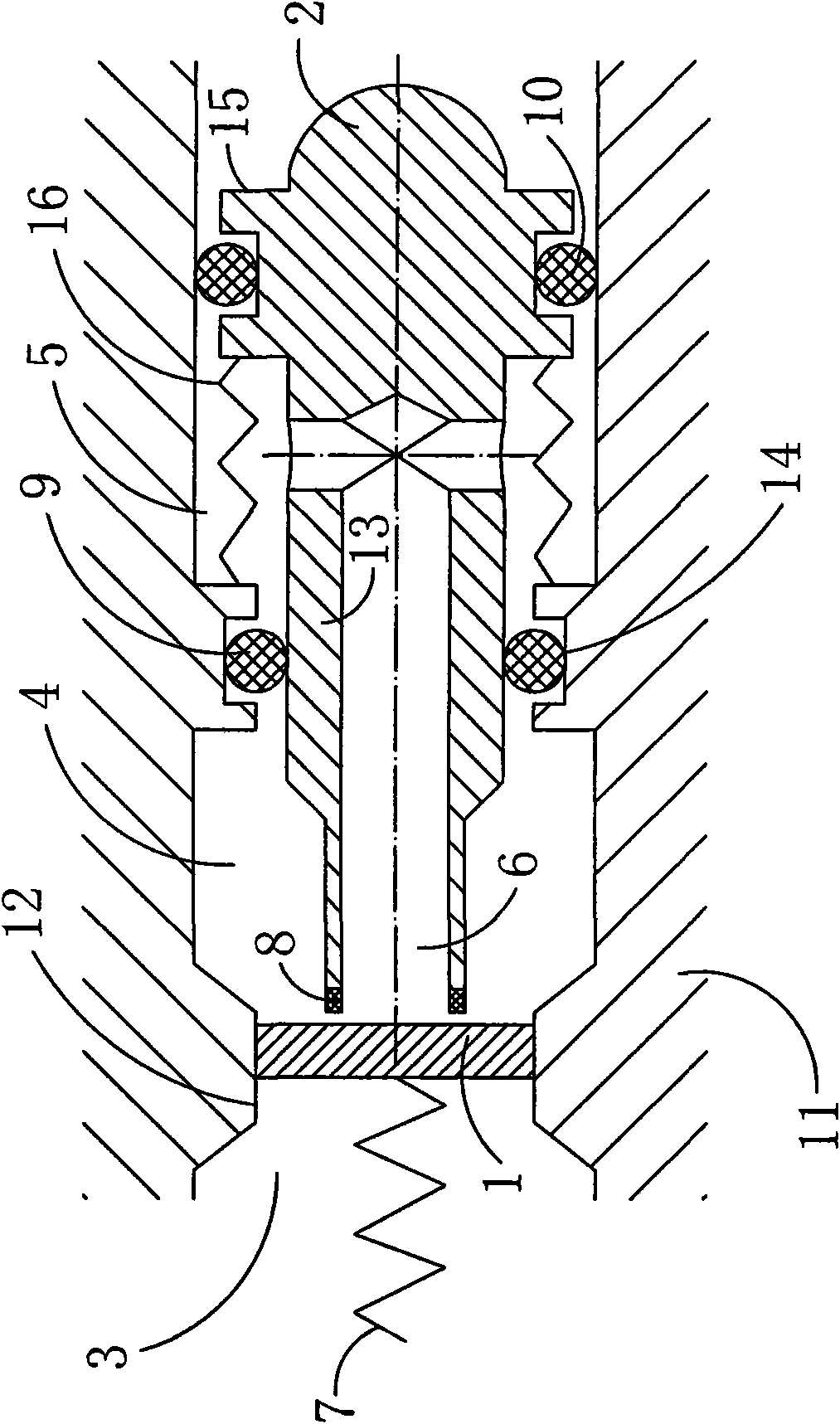
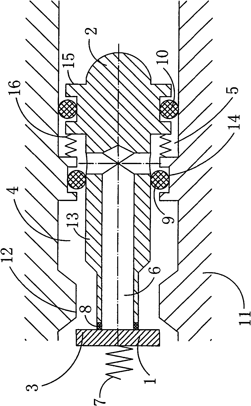
[0024] see figure 1 , the present invention is a valve used in a shifting device of an engineering vehicle,

[0025] It includes a valve body 11, a valve seat 1 disposed in the valve body 11, a valve stem 2 and a first spring 7, wherein one end of the valve seat 1 is fixedly connected to one end of the first spring 7, and the other end is in contact with the valve stem 2, The valve seat 1 is in contact with the first boss 12 provided on the valve body 11; the first prism 13 on the valve stem 2 is in contact with the second boss 14 arranged on the valve body 11; the valve stem 2 The second prism 15 on the top is in contact with the valve body 11,

[0026] Wherein, the valve body 11, the valve seat 1 and the first boss 12 form the air inlet 3, and the valve body 11, the valve seat (1), the valve stem 2, the first boss 12 and the second boss 14 form the control port 4 ; The valve body 11, the valve stem 2, the second boss 14 and the second prism 15 constitute the exhaust port 5...


PUM


Abstract

The invention relates to a valve used in shifting devices of engineering automobiles. The valve comprises a valve body, a valve seat arranged in the valve body, a valve rod and a first spring, whereinthe valve body, the valve seat and a first boss form a gas inlet; the valve body, the valve seat, the valve rod, the first boss and a second boss form a control port; the valve body, the valve rod, the second boss and a second frustum form an exhaust port; a medium channel is arranged in the valve rod; the medium channel is communicated with the control port and the exhaust port respectively; thecontact part of the valve rod and the valve seat is provided with a first sealing piece; the contact part of a first frustum on the valve rod and the second boss arranged on the valve body is provided with a second sealing piece; the contact part of the second frustum on the valve rod and the valve body is provided with a third sealing piece; and a second spring is arranged between the second boss and the second frustum. The valve overcomes the defects that valves in the prior art are large in volume, complex in structure and high in probability of breaking down in use. The valve has the advantages of compact structure, convenient manufacture and installation and reliable use.

Description

technical field [0001] The invention relates to a valve, in particular to a valve used in a shifting device of an engineering vehicle. Background technique [0002] In the prior art, the valves used in the shifting devices of engineering vehicles are large in size and complex in structure, and have a high probability of failure during use. Contents of the invention [0003] The object of the present invention is to provide a valve used in the shifting device of an engineering vehicle, so as to overcome the technical defects of large volume, complex structure and high probability of failure during use. [0004] Technical solution of the present invention is: [0005] 1. A valve used in a shifting device of an engineering vehicle, characterized in that: [0006] including a valve body, a valve seat arranged in the valve body, a valve stem and a first spring, [0007] One end of the valve seat is fixedly connected to one end of the first spring, and the other end is in con...

Claims


Application Information

Patent Timeline
Patent Type & Authority Applications(China)
IPC IPC(8): F16H61/30
Inventor 周养伦李清付
Owner XIAN AEROSPACE YUANZHENG FLUID CONTROL
Learn More