Three-chamber automatic clamping and locking mechanism

A locking mechanism and automatic technology, applied in the direction of clamping, metal processing mechanical parts, supports, etc., can solve the problems of poor clamping firmness, easy to loose, no self-locking function, etc., to achieve firm clamping of workpieces and flexible movements. Reliable, simple structure effect

Inactive Publication Date: 2011-05-04
DALIAN HUAGEN MACHINERY
View PDF0 Cites 0 Cited by
  • Summary
  • Abstract
  • Description
  • Claims
  • Application Information

AI Technical Summary

Problems solved by technology

[0002] The workpiece needs to be clamped during machining. It is very important whether it is firm after clamping and fixing. At present, the commonly used clamping mechanism has no self-locking function, and the clamping firmness is poor. It is easy to loosen during the processing of the workpiece, which affects the processing. precision

Method used


Image

  • Three-chamber automatic clamping and locking mechanism
  • Three-chamber automatic clamping and locking mechanism
  • Three-chamber automatic clamping and locking mechanism

Examples


Embodiment Construction

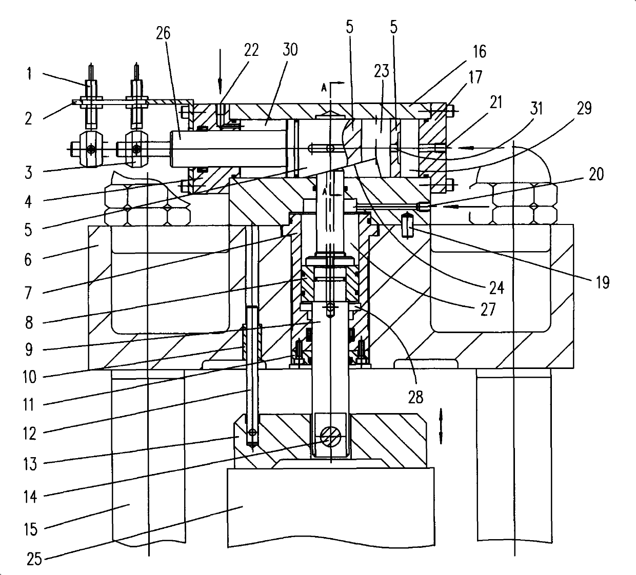
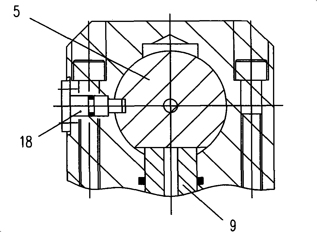
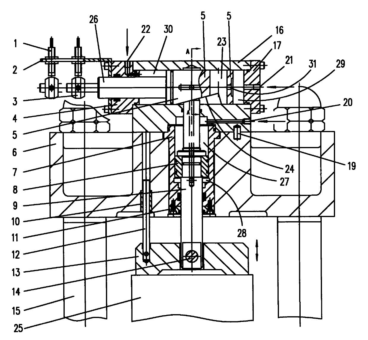
[0010] Such as figure 1 , 2 Shown: 6 is the upper cover supported by the pillar 15. The upper cover 6 is inlaid with a clamping oil cylinder 7 connected to the hydraulic control device in the middle position, and a clamping piston 8 matched with the clamping oil cylinder 7 is sleeved in On the clamping piston rod 9, the lower end of the clamping piston rod 9 is connected with a pressure plate 13 through a pin 14. A dust cover 11 is screwed to the bottom end of the crimping cylinder 7.

[0011] The upper end of the clamping piston rod 9 extends to the inner cavity of the locking cylinder 16 which is located above the upper cover 6 and is perpendicular to the clamping cylinder 7. The locking piston 5 in the locking cylinder 16 is processed with an inclined surface 24 to match the inclined surface on the upper end of the clamping piston rod 9. The locking piston 5 is machined with a radial piston rod inlet hole 23 and an axial oil hole 31. The right cavity 29 passes through the oil...


PUM


Abstract

The invention discloses a three-chamber automatic clamping and locking mechanism, which comprises an upper cover body, wherein the upper cover body is provided with a clamping oil cylinder which is connected with a hydraulic control device, a clamping piston matched with the clamping oil cylinder is connected with a clamping piston rod, the lower end of the clamping piston rod is connected with aplaten, and the upper end of the clamping piston rod extends into an inner chamber of a locking oil cylinder which is positioned above the upper cover body and is arranged perpendicular to the clamping oil cylinder; a locking piston arranged inside the locking oil cylinder is provided with an inclined surface which is matched with an inclined surface at the upper end of the clamping piston rod; and a right chamber positioned on the right side of the locking piston inside the locking oil cylinder is communicated with a lower chamber below the clamping piston inside the clamping oil cylinder through a hydraulic oil passage on the clamping piston rod. When the mechanism works, the clamping piston rod compacts a workpiece downward through the platen, the inclined surface at the locking pistonabove the clamping piston rod plays a role of compacting the upper end of the clamping piston rod at this time, and the mechanism plays a role in self-locking for the compaction of the workpiece, ensures that the clamped workpiece is firm and does not loosen, and has a simple integral structure, and flexible and reliable action.

Description

Technical field [0001] The invention relates to a workpiece clamping mechanism, in particular to a three-cavity automatic clamping and locking mechanism, which is used for clamping machining workpieces. Background technique [0002] The workpiece needs to be clamped during machining. It is very important whether the clamping is firm or not. The currently commonly used clamping mechanism has no self-locking function, and the clamping firmness is poor. It is easy to loosen during the processing of the workpiece, which affects the processing. Accuracy. Summary of the invention [0003] The purpose of the present invention is to provide a three-cavity automatic clamping and locking mechanism that is firm in clamping, has a self-locking function, satisfies large stroke clamping, and improves workpiece processing accuracy, and overcomes the deficiencies of the prior art. [0004] The three-chamber automatic clamping and locking mechanism of the present invention includes an upper cover 6...

Claims


Application Information

Patent Timeline
Patent Type & Authority Patents(China)
IPC IPC(8): B23Q3/06
Inventor 杨曙光吴长江陈永龙
Owner DALIAN HUAGEN MACHINERY
Why Eureka
Try Eureka