Dissipating device

A technology of heat dissipation device and heat dissipation fins, applied in indirect heat exchangers, heat exchange equipment, lighting and heating equipment, etc., can solve the problems of increasing the combined noise of heat dissipation devices, increasing fan noise or abnormal sound, etc. Efficiency, noise reduction effect

Inactive Publication Date: 2009-11-11
韩超 +3
View PDF1 Cites 3 Cited by
  • Summary
  • Abstract
  • Description
  • Claims
  • Application Information

AI Technical Summary

Problems solved by technology

[0005] As we all know, the fan will vibrate during the working process, which will increase the noise or abnormal sound of the fan operation. Since the fan of the above cooling device combination is directly fixed to the top of the radiator through a fan fixing piece, the vibration generated by the fan during work will be Acting on the radiator, increasing the noise of the radiator combination

Method used


Image

  • Dissipating device
  • Dissipating device
  • Dissipating device

Examples


Embodiment Construction

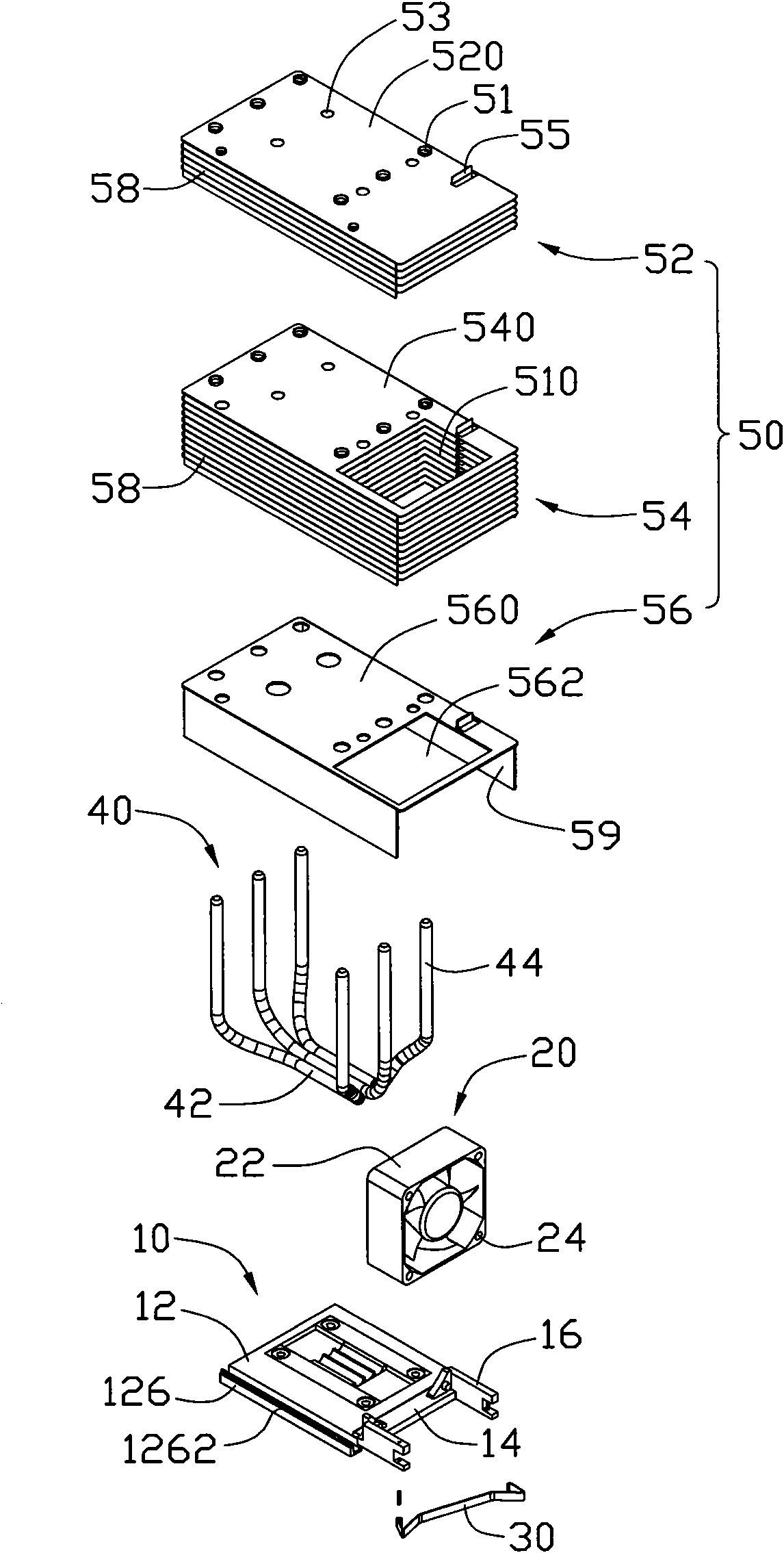
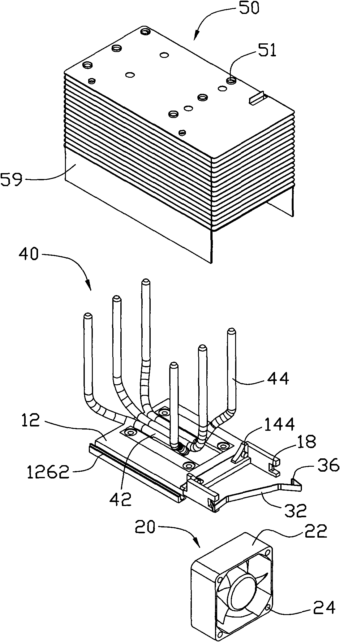
[0014] see figure 1 , the heat dissipation device of the present invention is used to dissipate heat to an electronic component (not shown), which includes a base 10 in contact with the electronic component, a fan 20 placed on the base 10, and a buckle for fixing the fan 20 to the base 10 Tool 30 , several heat pipes 40 installed on the base 10 and a cooling fin set 50 placed on the base 10 and through which the heat pipes 40 pass.

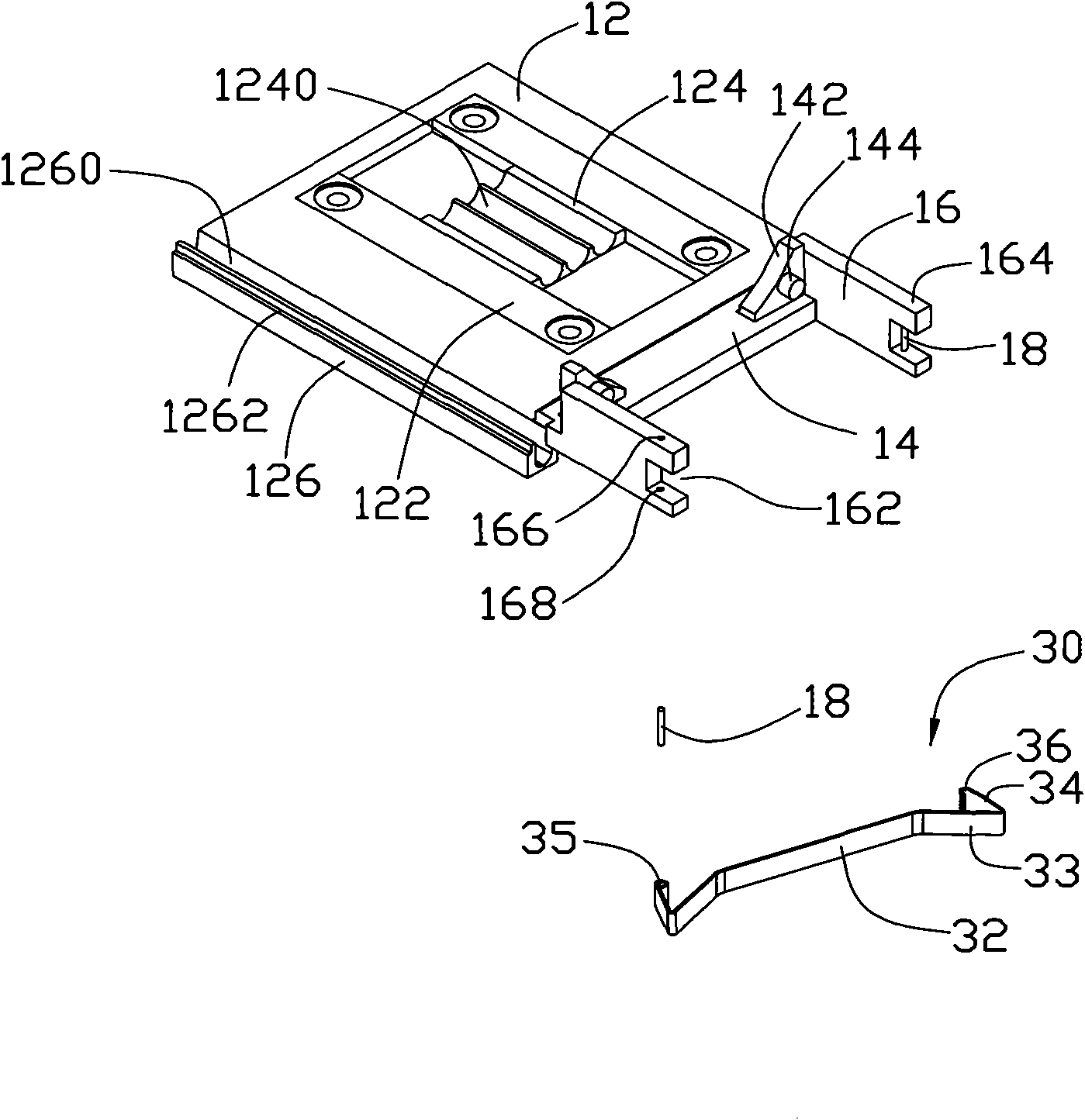
[0015] The above-mentioned base 10 includes a substantially square body 12, a connecting plate 14 extending horizontally outward from one end of the body 12, and two mounting plates extending outward horizontally from opposite ends of the connecting plate 14 perpendicular to the connecting plate 14. plate 16.

[0016] Please also see figure 2 A rectangular opening (not shown) is defined on the body 12 of the base 10 for receiving a substrate 122 . The base plate 122 is close to one side of the body 12 of the base 10 and away from the other opp...


PUM


Abstract

The invention relates to a dissipating device which is used for dissipating heat generated by an electronic element. The dissipating device comprises a base in contact with the electronic element, a plurality of dissipating fins formed on the base and a fan arranged on the base, wherein the dissipating fins are provided with an accommodating space for accommodating the fan; and the fan and the dissipating fins are arranged at intervals. Compared with the prior art, when the dissipating device is used, air flows generated by the fan not only flow away from gaps among the dissipating fins, but also flow away from through holes on the dissipating fins so as to increase the dissipating efficiency of the dissipating device. The fan is directly arranged on the base and accommodated in the accommodating space of the dissipating fins so as to avoid directly contacting the dissipating fins. Thus, the fan cannot frequently collide with the dissipating fins to generate noise in a vibration process, and the vibration of the dissipating fins because of the contact of the fan and the dissipating fins cannot be caused so as to reduce the noise of the dissipating device.

Description

technical field [0001] The invention relates to a heat dissipation device, in particular to a heat dissipation device with a fan fixing device. Background technique [0002] With the continuous development of the electronic information industry, the operating frequency and speed of electronic components are also increasing. High frequency and high speed will cause more and more heat generated by electronic components, and the temperature will become higher and higher, which will seriously affect the performance and stability of electronic components during operation. In order to ensure the normal operation of electronic components, it is necessary to discharge the electronic components in time Generates a lot of heat. For this reason, the industry usually installs a heat dissipation device on the surface of these heat-generating electronic components to assist in heat dissipation. [0003] US Pat. No. 6,667,884 discloses a heat sink assembly, which includes a heat sink mou...

Claims


Application Information

Patent Timeline
Patent Type & Authority Applications(China)
IPC IPC(8): H05K7/20H01L23/34H01L23/40H01L23/467
CPCF28F1/32H01L23/467H01L23/427F28D15/0266H01L2924/0002H01L2924/00
Inventor 李伟吴宜强陈俊吉
Owner 韩超
Why Eureka
Try Eureka