
Light control device and lamp strip

A control device and lighting control technology, applied in lighting devices, energy-saving control technology, lamp circuit layout, etc., can solve the problems of troublesome line connection, high cost, complicated lines, etc., achieve accurate lighting control, facilitate mutual cascading, reduce cost effect

Inactive Publication Date: 2012-07-25
刘昌贵
View PDF5 Cites 0 Cited by
  • Summary
  • Abstract
  • Description
  • Claims
  • Application Information

AI Technical Summary

Problems solved by technology

[0003] When the existing neon light control device controls the "brightness" and "darkness" of the LED light source, multiple, multi-row single-chip microcomputers are used to make multiple, multiple, clustered, or follow a certain pattern, pattern sequence or timing by setting corresponding programs. "On" and "off" automatically realize the flow of LED light sources or the transformation of patterns, but the existing technology uses a single-chip microcomputer for control, resulting in complicated wiring and troublesome wiring connections, which cannot be cascaded with each other, and cannot be applied due to high costs. into small light strips

Method used


Image

  • Light control device and lamp strip
  • Light control device and lamp strip
  • Light control device and lamp strip

Examples


Embodiment Construction

[0015] Embodiments of the present invention will be described in further detail and clearly below in conjunction with the accompanying drawings.

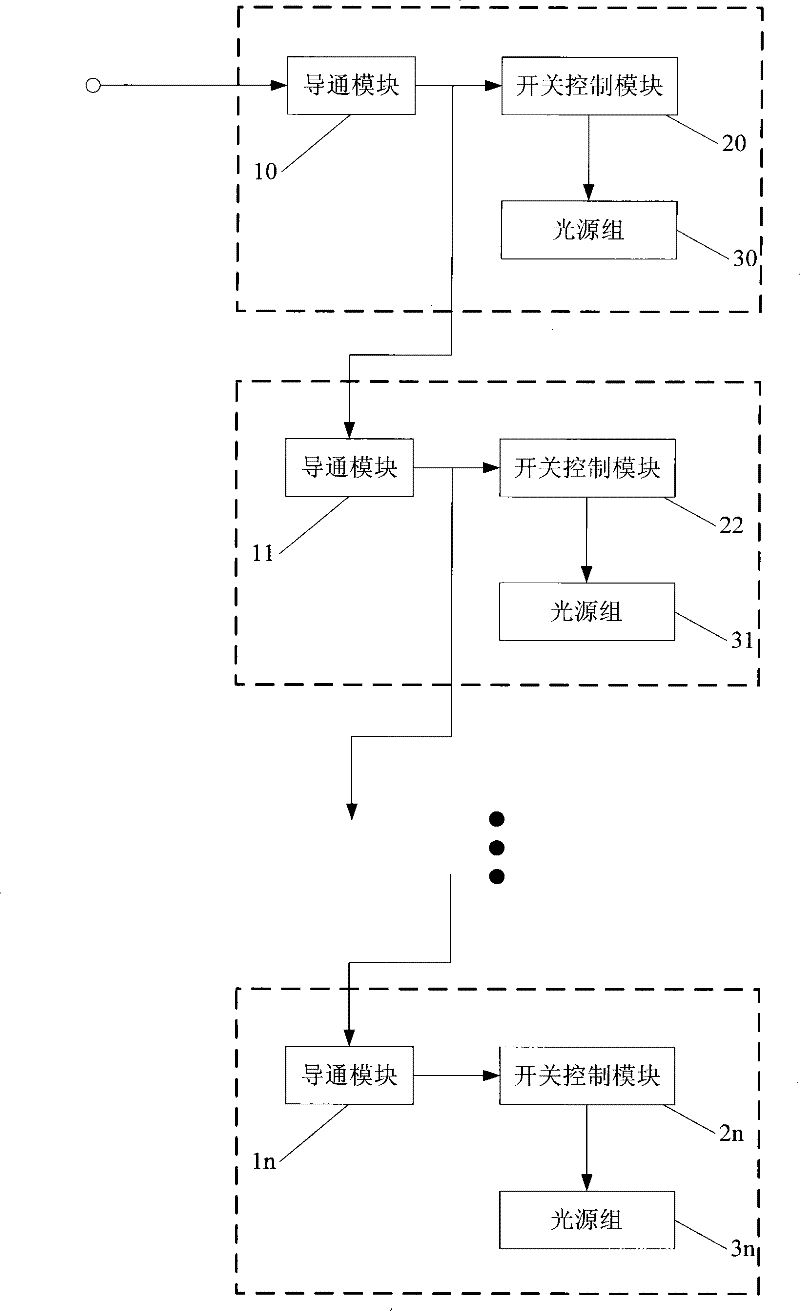
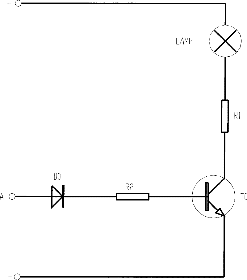
[0016] figure 1 It is a schematic structural diagram of a specific embodiment of the control circuit unit of the lighting control device according to the embodiment of the present invention, as shown in figure 1 As shown, each control circuit unit includes a conduction module 10, a switch control module 20, and a light source group 30; the conduction module 10 is connected to the switch control module 20; the switch control module 20 is connected to the light source group 30 In specific implementation, the device in the embodiment of the present invention includes several control circuit units, the switch control modules of each of the control circuit units are connected in parallel, the light source groups are connected in parallel, and the conduction modules are sequentially connected in series catch. Further, the conduction mod...


PUM


Abstract

The embodiment of the invention discloses a light control device. The device comprises a plurality of cascaded control circuit units, and each control circuit unit comprises a conduction module, a switch control module and a light source group; the conduction module is connected with the switch control module; the switch control module is connected with the light source group; and the switch control modules of the control circuit units are mutually connected in parallel, the light source groups are mutually connected in parallel, and the conduction module are subsequently connected in series.In addition, the embodiment of the invention also discloses a lamp strip. By implementing the embodiment of the invention, the lamp strip or a lamp string light source is controlled by adopting fewerand simple electronic elements, the time sequence flow of the light is realized, and the cost can be reduced; and connecting wires among unit circuits are fewer so as to carry out mutual cascade connection conveniently; and simultaneously the unit circuits are not mutually interfered and can accurately control the light.

Description

technical field [0001] The invention relates to the field of light-emitting advertisements, in particular to a light control device and a light strip. Background technique [0002] Neon lights are usually used for decoration on city streets, bridgeheads, building outlines, advertising boards, etc. In order to increase the beautification effect, after installing a controller, the colored light strips or light strings can be turned on and off sequentially at different time intervals, which will make people Produce the visual effect that the lights are flowing or running and moving. [0003] When the existing neon light control device controls the "brightness" and "darkness" of the LED light source, multiple, multi-row single-chip microcomputers are used to make multiple, multiple, clusters, or according to a certain pattern, pattern sequence or timing by setting corresponding programs. "On" and "off" automatically realize the flow of LED light sources or the transformation of...

Claims


Application Information

Patent Timeline
Patent Type & Authority Patents(China)
IPC IPC(8): F21S4/00H05B37/02F21V23/00
CPCY02B20/42Y02B20/40
Inventor 刘昌贵
Owner 刘昌贵
Learn More