
Bearing device and manufacture method of flexible display panel

A technology for a display panel and a carrying device, which is applied to auxiliary devices, manufacturing tools, nonlinear optics, etc., can solve the problems of poor production yield of flexible display panels, inconvenience, and general products and methods that do not have suitable structures and methods. , to achieve the effect of preventing laser damage to the drive circuit module, technological progress, and improving the yield of high-quality production

Active Publication Date: 2009-11-11
E INK HLDG INC
View PDF0 Cites 15 Cited by
  • Summary
  • Abstract
  • Description
  • Claims
  • Application Information

AI Technical Summary

Problems solved by technology

Even so, due to the energy distribution, interference, and diffraction of the laser itself, it is still difficult for the drive circuit module to be completely free from the influence of the laser, resulting in a poor production yield of the flexible display panel.
[0007] It can be seen that the above-mentioned existing manufacturing method of the carrying device and the flexible display panel obviously still has inconveniences and defects in product structure, manufacturing method (processing method) and use, and needs to be further improved urgently.
In order to solve the above-mentioned problems, the relevant manufacturers have tried their best to find a solution, but no suitable design has been developed for a long time, and there is no suitable structure and method for general products and methods to solve the above-mentioned problems. This is obviously a problem that relevant industry players are eager to solve

Method used


Image

  • Bearing device and manufacture method of flexible display panel
  • Bearing device and manufacture method of flexible display panel
  • Bearing device and manufacture method of flexible display panel

Examples


Embodiment Construction

[0046] In order to further explain the technical means and effects of the present invention to achieve the intended purpose of the invention, the specific implementation methods, Structure, method, step, feature and effect thereof are as follows in detail.

[0047] The aforementioned and other technical contents, features and effects of the present invention will be clearly presented in the following detailed description of preferred embodiments with reference to the drawings. Through the description of the specific implementation mode, when the technical means and functions adopted by the present invention to achieve the predetermined purpose can be obtained a deeper and more specific understanding, but the accompanying drawings are only for reference and description, and are not used to explain the present invention be restricted. The directional terms mentioned in the following embodiments, such as: up, down, left, right, front or back, etc., are only directions referring ...


PUM

PropertyMeasurementUnit
Wavelengthaaaaaaaaaa

Abstract

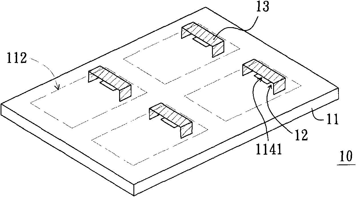
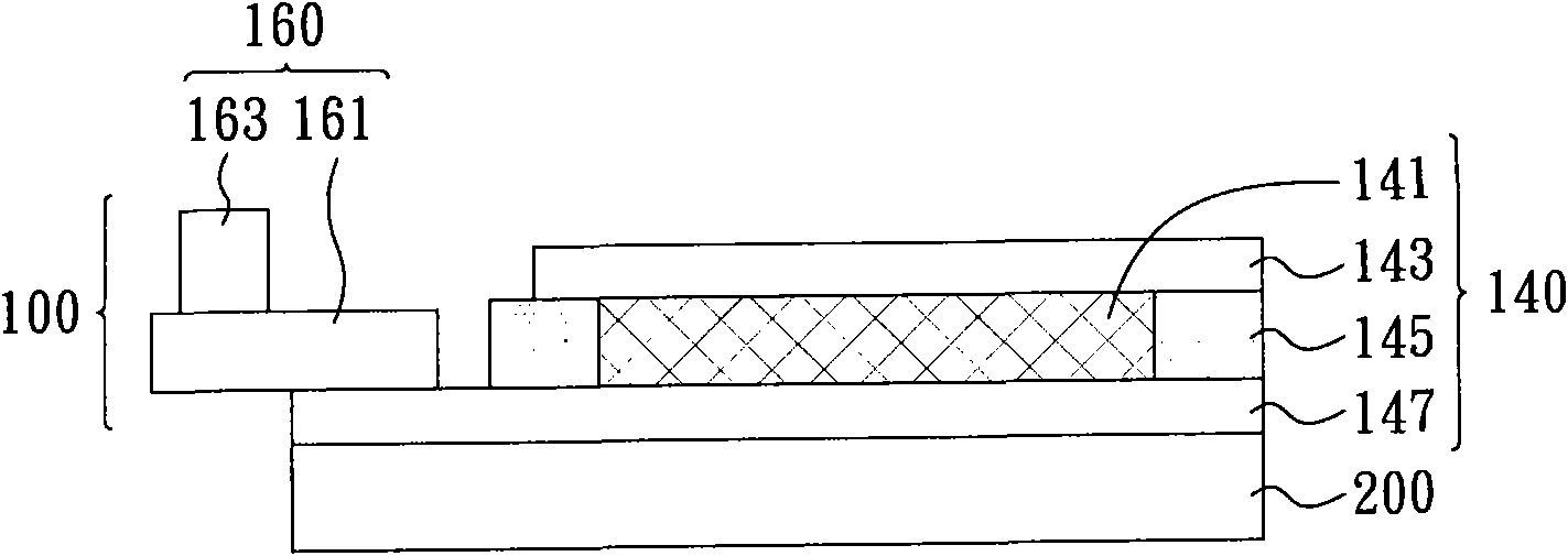
The invention relates to a bearing device and a manufacture method of a flexible display panel. The bearing device is suitable for a laser separation procedure and bears at least one flexible display panel. The flexible display panel is formed on a transparent substrate and comprises a display body and a drive circuit die set. The bearing device comprises a bearing plate and at least one protection cover, wherein the bearing plate is provided with at least one bearing area for bearing the flexible display panel, and the protection cover is arranged on the bearing plate and positioned at the edge of the bearing area. A containing space is formed between the protection cover and the bearing plate for containing the drive circuit die set. The protection cover covers the drive circuit die set to prevent laser from irradiating on the drive circuit die set. The manufacture method of the flexible display panel comprises the following steps: the flexible display panel is manufactured on the transparent substrate and comprises the display body and the drive circuit die set connected with the edge of the display body; the drive circuit die set of the flexible display panel is covered; and the laser separation procedure is carried out to separate the transparent substrate and the flexible display panel. The invention can prevent the laser from damaging the drive circuit die set and enhance the qualified rate of the flexible display panel.

Description

technical field [0001] The present invention relates to a display panel, in particular to a method for manufacturing a flexible display panel that can avoid laser damage to a drive circuit module and improve the yield of flexible display panels, and a carrying device therefor. Background technique [0002] A thin film transistor liquid crystal display panel (TFT LCD Panel) generally includes a glass substrate, a transparent protective layer opposite to the glass substrate and arranged at intervals, a liquid crystal layer arranged between the glass substrate and the transparent protective layer, and a driving circuit module. Group. A thin film transistor array and multiple pixel electrodes are arranged on the glass substrate, and a common electrode is arranged on the transparent protective layer. The driving circuit module is electrically connected with the thin film transistor array, the pixel electrode and the common electrode for controlling the thin film transistor liqui...

Claims


Application Information

Patent Timeline
IPC IPC(8): B23K26/36B23K26/42B23K37/02G02F1/167
Inventor 辛哲宏苏鸿滨郑瑞忠王以靓
Owner E INK HLDG INC
Learn More