Dehumidifier
A dehumidifier and dehumidification wheel technology, applied in the directions of deicing, separation method, heating method, etc., can solve the problems of uneven internal flow, small indoor air heat exchange area, low heat exchange efficiency, etc., to improve dehumidification performance, size Compact, smooth flow of regeneration air
- Summary
- Abstract
- Description
- Claims
- Application Information
AI Technical Summary
Problems solved by technology
Method used
Image

Examples
no. 1 example
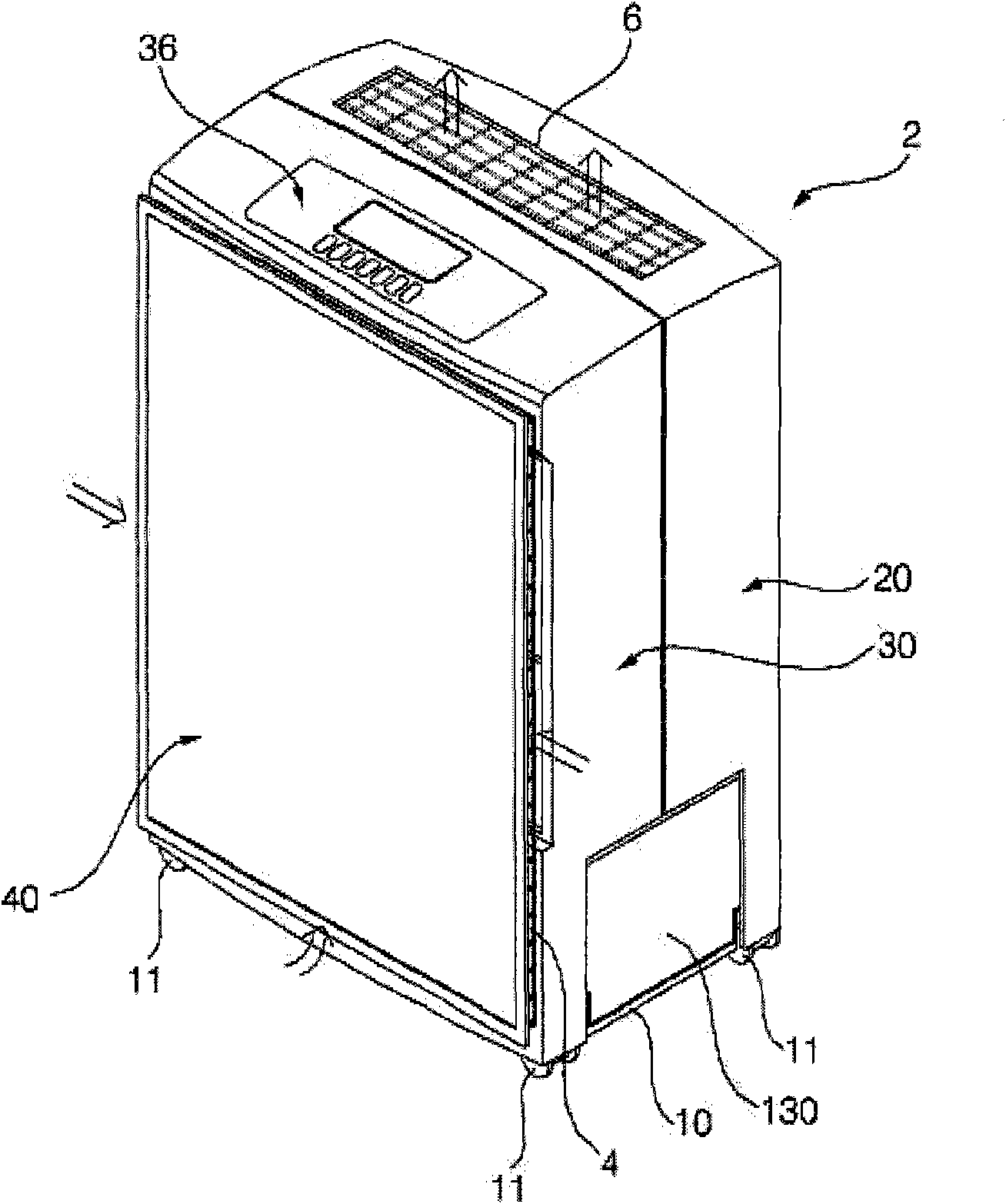
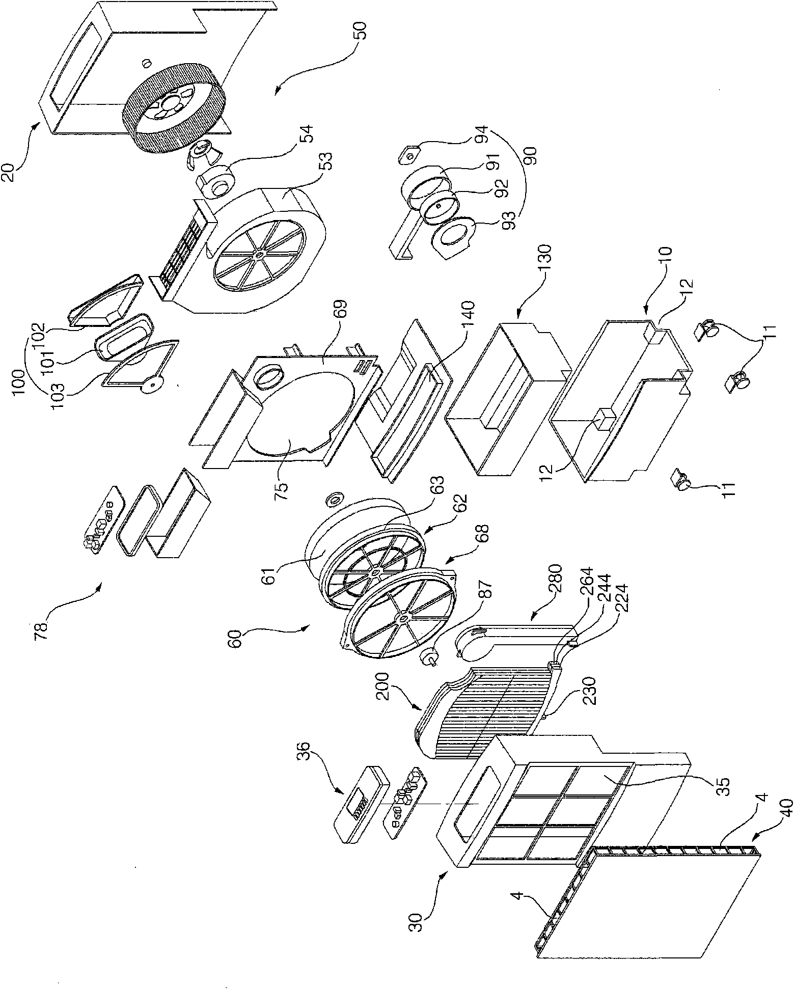
[0033] figure 1 is a perspective view of a dehumidifier according to a first embodiment of the present invention, figure 2 for the above figure 1 An exploded perspective view of the main parts of the dehumidifier shown.
[0034] refer to figure 1 as well as figure 2 , the overall configuration of the dehumidifier according to the first embodiment of the present invention will be described.
[0035] Such as figure 1 As shown, in the dehumidifier according to this embodiment, the dehumidified indoor air is discharged after inhaling indoor air to absorb moisture, and the main body 2 is formed with an air intake part 4 and an air discharge part 6 .
[0036] Such as figure 2 As shown, the body 2 includes: a base 10; a rear case 20, which is combined with the rear portion of the base 10; a front case 30, which is arranged in front of the rear case 20; a front panel 40, which is connected to the front case 30 Combine.
[0037] The base 10 is used to form the bottom surface...
no. 2 example
[0118] Figure 7 It is a perspective view of the second embodiment of the present invention.
[0119] refer to Figure 7 The overall configuration of the second embodiment of the present invention will be described. The overall structure of the second embodiment of the present invention is similar to that of the above-mentioned first embodiment. In the following, description will be made focusing on the differences of the second embodiment.
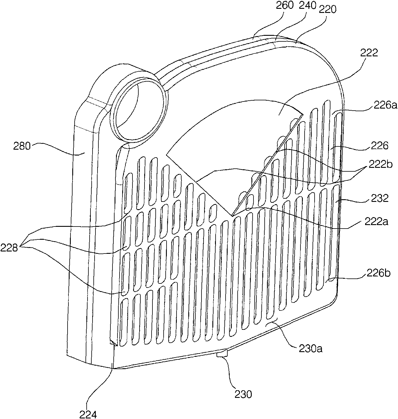
[0120] In the first reconditioning air inflow portion 322 of the first heat exchange plate 220 according to the second embodiment of the present invention, a portion spaced upward by a predetermined distance from the center 322a of the condensing heat exchanger is closed. The dehumidification wheel 60 has a rotating part at the center so that reconditioning air cannot flow into the first reconditioning air inflow part 222 through a portion where the rotating part is located. Therefore, the part where the rotation part of the said dehu...
no. 3 example
[0123] Figure 8 It is a transverse sectional view of the third embodiment of the present invention.
[0124] refer to Figure 8 The overall configuration of the third embodiment of the present invention will be described. The overall structure of the third embodiment of the present invention is similar to that of the above-mentioned first embodiment. In the following, description will be made focusing on the differences of the third embodiment.
[0125] When the reconditioning air discharge parts 224, 244, 264 are located on the left and right sides of the condensing heat exchanger, unevenness may occur in the flow of air flowing in the condensing flow path. Specifically, the reconditioning air that has passed through the condensation channels 426, 446, 466 near the reconditioning air discharge parts 224, 244, 264 can be discharged to the reconditioning air discharge parts 224, 244, 264 in a short time. . Furthermore, the reconditioning air passing through the condensing...
PUM
 Abstract
Description
Claims
Application Information
 - R&D
- Intellectual Property
- Life Sciences
- Materials
- Tech Scout
- Unparalleled Data Quality
- Higher Quality Content
- 60% Fewer Hallucinations
Browse by: Latest US Patents, China's latest patents, Technical Efficacy Thesaurus, Application Domain, Technology Topic, Popular Technical Reports.
© 2025 PatSnap. All rights reserved.Legal|Privacy policy|Modern Slavery Act Transparency Statement|Sitemap|About US| Contact US: help@patsnap.com