Drain structure of air cleaner for motorcycle

A technology for air filters and motorcycles, which is applied to fuel air filters, vehicle components, and power plant gas intake, etc., can solve the problem of increased production costs, poorer design freedom of motorcycle casings, and control flexibility. It can reduce assembly work, improve design freedom, and reduce production costs.

Active Publication Date: 2009-11-04
YAMAHA MOTOR CO LTD
View PDF0 Cites 2 Cited by
  • Summary
  • Abstract
  • Description
  • Claims
  • Application Information

AI Technical Summary

Problems solved by technology

[0002] For various known motorcycles, in order to reduce the chance of water being sucked into the air inlet of the air filter, some motorcycle air filters use rubber hoses to extend the air inlet to an anhydrous place; or In addition, the drainage structure A of the air filter 21 for some motorcycles is as follows: Figure 5 and Image 6 As shown, although baffles 23 and ribs 24 are respectively arranged on the periphery and the rear of the air inlet 22, it is used to reduce the chance of the water sprayed on the outer cover surface of the air filter 21 flowing to the air inlet 22, But the structure of baffle plate 23 and rib 24 can destroy the attractive in appearance of original motorcycle, reduce the consumer's willingness to buy, and its protruding structure towards the front side and the outside is not only occupying space, but also easily with the shock absorber up and down. The swinging body shells 25 interfere with each other, so a considerable clearance tolerance must be maintained between the body shell 25 and the fender 23 and ribs 24
The drainage structure of such a known motorcycle air filter will cause the design freedom of the motorcycle shell to deteriorate, and the width of the vehicle body will be too wide, which will greatly reduce the flexibility and lightness of the vehicle. The plate 23 and the rib 24 need to increase the cost of parts and assembly work, so the structure that reduces the water being sucked into the air cleaner has concerns about increased production cost and poor production workability.

Method used


Image

  • Drain structure of air cleaner for motorcycle
  • Drain structure of air cleaner for motorcycle
  • Drain structure of air cleaner for motorcycle

Examples


Embodiment Construction

[0025] Hereinafter, the embodiments of the present invention will be described in detail with reference to the drawings.

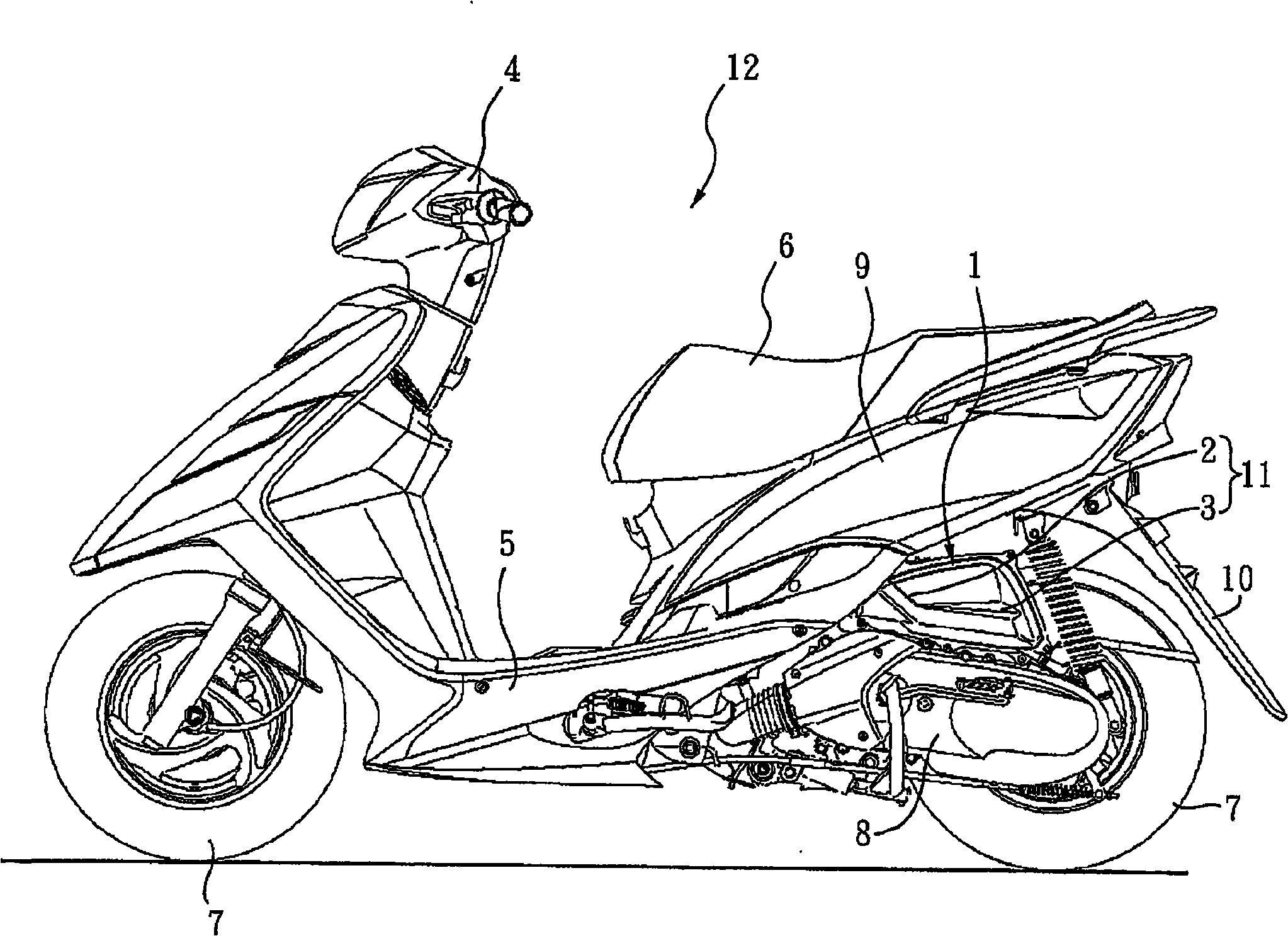
[0026] figure 1 It is a side view of a motorcycle including the drainage structure of the air cleaner for motorcycle of the present invention. figure 1 Although it is shown that the drainage structure 11 of the air cleaner for motorcycles of the present invention is applied to a scooter-type motorcycle, the present invention is not limited to be applied to a scooter-type motorcycle, and may also be other types of motorcycles. Vehicles, such as gear-mounted motorcycles, and powered vehicles. Powered vehicles are, for example, all-terrain vehicles (ATV) and snowmobiles.

[0027] Such as figure 1 As shown, a side view of a motorcycle 12 having a drainage structure 11 of an air cleaner for a motorcycle of the present invention has: an air cleaner 1, a front 4, a pedal 5, a seat part 6, a wheel 7, and a transmission mechanism 8. The car body shell 9 and the rea...


PUM


Abstract

The invention relates to a drain structure of an air cleaner for a motorcycle, which utilizes the shape of an outer cover of the air cleaner to form a gradient structure with different heights so as to induce water sprayed to the outer cover, change the flow direction of the cover and avoid the problems that a great deal of water flows to a position near an air entry and is absorbed into the air cleaner, so that air amount needed by an engine can not be provided, the performance of the engine is reduced or the engine is extinguished due to the blockage of filter medium in the air cleaner caused by water or mud and sand carried by the water. The drain structure of the air cleaner for the motorcycle is arranged on the outer cover of the air cleaner for the motorcycle and used for reducing water absorbed into the air cleaner. The drain structure is characterized in that a gradient drain tank is arranged along the outer cover from the upper edge of the outer cover above the air entry of the air cleaner for the motorcycle; in two sides of the drain tank, the lower side is ridgier than the upper side; and the drain tank inclines towards the rear lower part and extends to the rear part of the air entry.

Description

Technical field [0001] The present invention relates to a drainage structure for reducing water intrusion into an air cleaner of a motorcycle, and more particularly to a drainage structure formed by an air cleaner housing body. Background technique [0002] In order to reduce the chance of water being sucked into the air inlet of the air cleaner in various known motorcycles, some air cleaners for motorcycles use a rubber hose to extend the air inlet to a place where there is no water; or In addition, the drainage structure A of the air cleaner 21 for some motorcycles is as follows: Figure 5 with Figure 6 As shown, although baffles 23 and ribs 24 are respectively arranged on the periphery and rear of the air inlet 22, they are used to reduce the chance of water sprayed on the outer cover of the air cleaner 21 from flowing to the air inlet 22, However, the structure of the baffle 23 and the ribs 24 will damage the appearance of the original motorcycle and reduce the consumer’s wi...

Claims


Application Information

Patent Timeline
IPC IPC(8): B60K13/02F02M35/04
Inventor 邓国栋
Owner YAMAHA MOTOR CO LTD
Why Eureka
Try Eureka