Five-face drilling-tapping central machine structure

A technology of center machine and shaft structure, which is applied to metal processing machinery parts, other manufacturing equipment/tools, driving devices, etc., can solve the problems such as the inability to add hydraulic clamps, inconvenience, slow moving speed, etc. The calibration process is convenient and safe, the cleaning of falling chips is convenient, and the processing speed is fast.

Inactive Publication Date: 2009-11-04
捷力精密机械股份有限公司
View PDF0 Cites 5 Cited by
  • Summary
  • Abstract
  • Description
  • Claims
  • Application Information

AI Technical Summary

Problems solved by technology

In this way, the machine table 1 is quite heavy and increases the manufacturing cost, and it is not lightweight enough. Moreover, when the worktable 2 needs to be moved for processing, because of the large space and heavy weight, the moving speed is slow and the processing efficiency is poor.
Furthermore, because the structure of the fourth axis and the fifth axis of the existing five-sided drilling and tapping center must include a worktable 2 and two supports 3 and be arranged on the saddle 5, chips will be generated during the machining process. The problem of poor performance often causes debris to accumulate between the workbench 2 and the two supports 3, which is difficult to clean and causes considerable inconvenience in cleaning.
[0003] In addition, the structure of the fourth axis and the fifth axis of the existing five-sided drilling and tapping center, wherein the rotating disk 4 rotates in the rotation direction 7 of the fifth axis, and the supporting body 3 generates The rotation direction 6 of the fourth axis will cause the operator to have a blind spot on the line of sight of the rotating disk 4 on the support body 3, which will cause inconvenience in the correction or processing process and cause operational danger.
The structure of the existing five-sided drilling and tapping center machine must include a workbench 2 and two supports 3 and be arranged on the saddle 5, so there is no space to connect the feeding structure below the rotating disk 4 or it cannot Additional design of the function of the hydraulic clamping fixture, etc.
Moreover, the fourth and fifth axes of the existing five-sided drilling and tapping center machine structure are located above the base, and the level and verticality must be adjusted during processing, which is quite inconvenient

Method used


Image

  • Five-face drilling-tapping central machine structure
  • Five-face drilling-tapping central machine structure
  • Five-face drilling-tapping central machine structure

Examples


Embodiment Construction

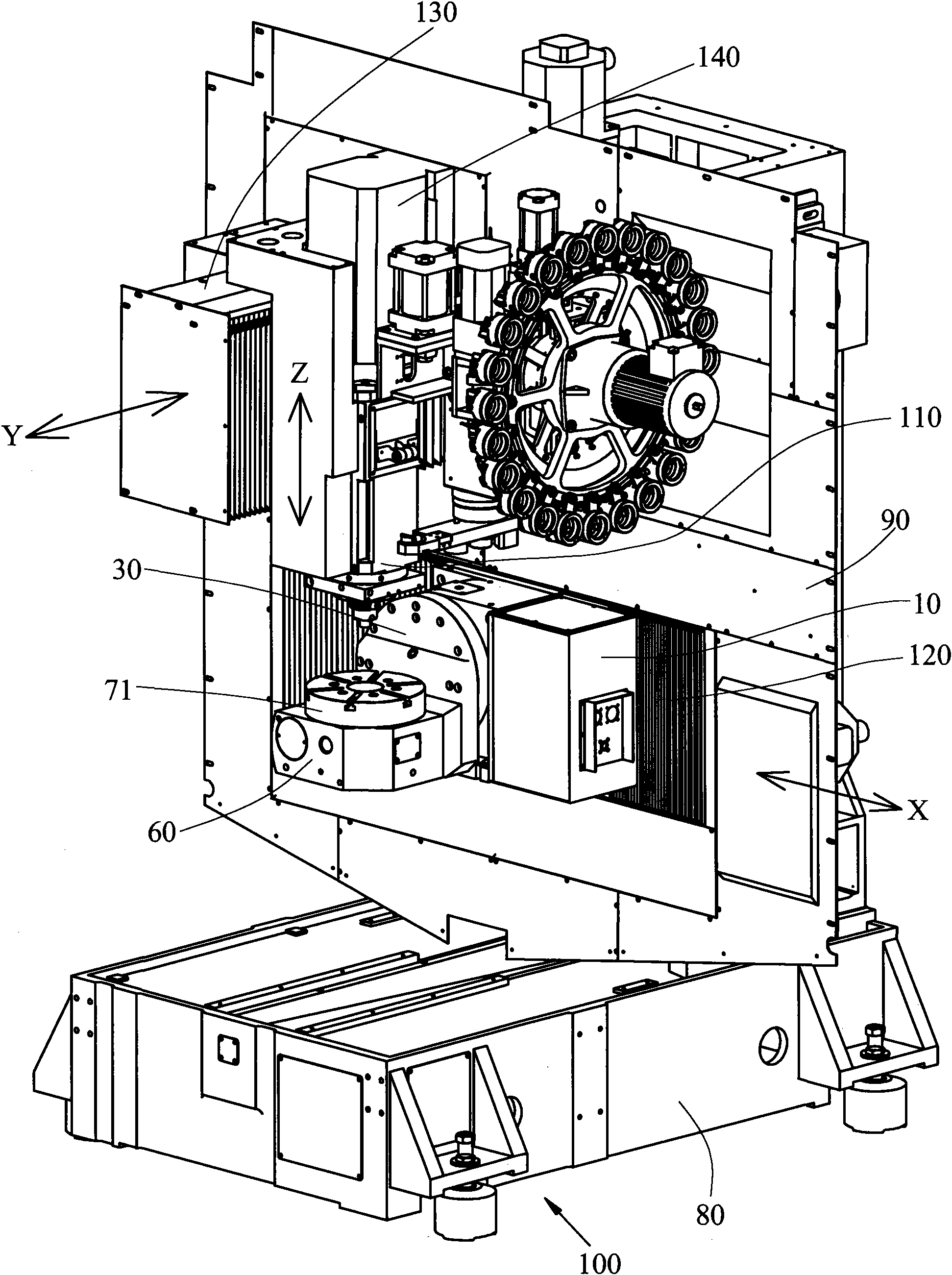
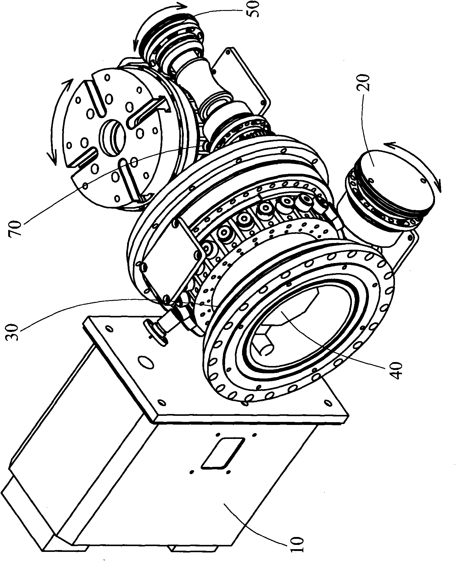
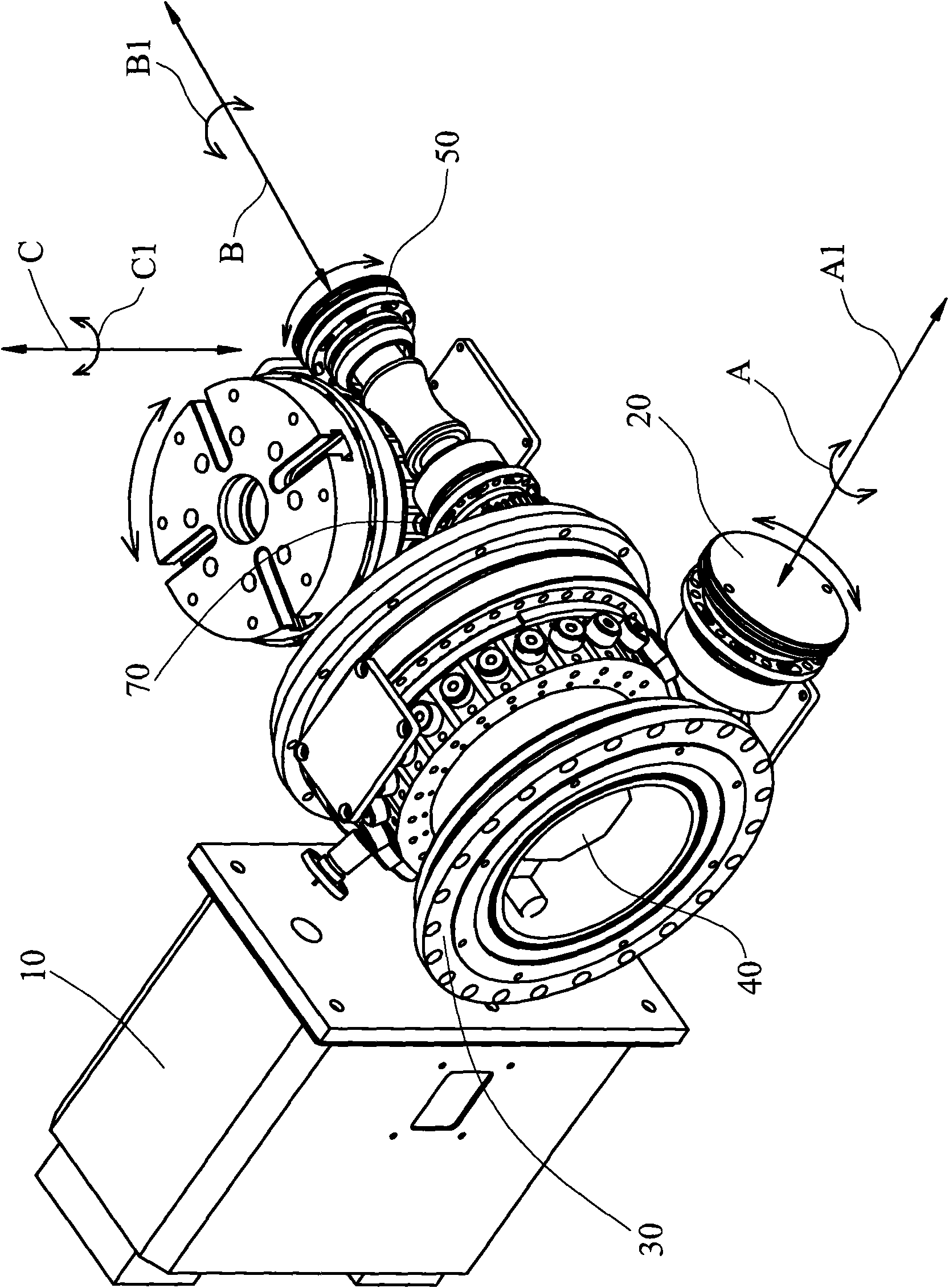
[0037] see Figure 1 ~ Figure 3 As shown, the present invention provides a five-sided drilling and tapping center machine structure, the fourth axis and the fifth axis structure are arranged on a machine platform 100, and the described machine platform 100 includes a base 80 and A column 90, the structure of the fourth shaft and the fifth shaft includes: a first servo motor 10, a first input shaft 20, a first output shaft roller 30, a second servo motor 40, a second The input shaft 50 , a supporting body 60 and a second output shaft roller 70 .

[0038]Wherein, the first servo motor 10 is electrically connected to a first power supply; the first output shaft roller 30 is a cam roller, and the first input shaft 20 corresponds to the first output shaft on the peripheral surface The roller 30 is provided with a tapered support rib not shown in the figure, the second output shaft roller 70 is a cam roller, and the second input shaft 50 is provided with a taper on the peripheral s...


PUM


Abstract

The invention relates to a five-face drilling-tapping central machine structure, the main structure of which comprises a board, a fourth shaft structure and a fifth shaft structure. The fourth shaft structure and the fifth shaft structure comprise a first servo motor, a first input shaft, a first output shaft roller, a second servo motor, a second input shaft, a support and a second output shaft roller, wherein the first input shaft can be transmitted by the first servo motor and can link the first output shaft roller to rotate by taking the B axis as a centre, meanwhile, the second servo motor can link the second input shaft which can link the second output shaft roller to rotate by taking the C axis as a centre. The five-face drilling-tapping central machine structure is safe, and has light weight, excellent piece falling property and better efficiency of processing and correcting processes.

Description

technical field [0001] The invention relates to the technical field of a five-sided drilling and tapping center machine, in particular to a five-sided drilling and tapping center machine structure that can effectively reduce the weight of the structure and has high processing efficiency. Background technique [0002] see Figure 4 As shown, the existing five-sided drilling and tapping center machine structure, in order to achieve the role of the fourth axis and the fifth axis structure, is to use a worktable 2 and two support bodies 3 to be arranged on the saddle 5, and the described The saddle 5 is located on a base. In this way, the machine table 1 is quite heavy and increases the manufacturing cost, and is not lightweight enough. Moreover, when the worktable 2 needs to be moved for processing, the moving speed is slow and the processing efficiency is poor because of the large space and heavy weight. Furthermore, because the structure of the fourth axis and the fifth axis...

Claims


Application Information

Patent Timeline
Patent Type & Authority Applications(China)
IPC IPC(8): B23P23/02B23Q5/10B23Q5/36
Inventor 曾国政陈建毓
Owner 捷力精密机械股份有限公司
Why Eureka
Try Eureka