
Pipe beveling machine

A beveling machine and pipe technology, applied in metal processing machinery parts, clamping, support, etc., can solve the problems of low production efficiency, inconvenient operation, difficult implementation, etc., and achieve high production efficiency, easy operation, consistent and accurate results

Inactive Publication Date: 2009-11-04
厦门中井科技有限公司
View PDF1 Cites 3 Cited by
  • Summary
  • Abstract
  • Description
  • Claims
  • Application Information

AI Technical Summary

Problems solved by technology

[0003] 1. Use a manual steel file to process the slope, and file the end face of the pipe into a slope (slope surface). However, the slope produced by a manual steel file has the disadvantage that the slope of the groove is difficult to grasp , and the production efficiency is low, and the labor intensity of the workers is high
[0004] 2. The inclination is machined with a machining lathe, and the machining accuracy is high. However, when machining large-diameter pipes, due to the large volume and heavy weight of the machining lathe, it brings a lot of inconvenience to on-site operations, handling and maintenance, and it is difficult to implement and increases costs.
[0005] 3. Use a portable electric angle grinder to process the slope. When it comes to pipeline (pipeline) maintenance, it is often necessary to replace part or all of the damaged pipeline, and the replaced pipeline port needs to be sloped by 20° to 50°. Welding or other connection after the groove, the groove is usually processed by a portable electric angle grinder, this kind of processing is time-consuming and laborious, and the processing quality cannot be guaranteed, and the groove angle is inconsistent
[0006] At present, there are also some related technical reports, each of which has its own advantages and disadvantages, but generally have disadvantages such as complex structure, inconvenient operation, and the need for special and complicated pipe clamping mechanisms, knife feeding mechanisms, and multiple knives.

Method used


Image

  • Pipe beveling machine
  • Pipe beveling machine
  • Pipe beveling machine

Examples


Embodiment 1

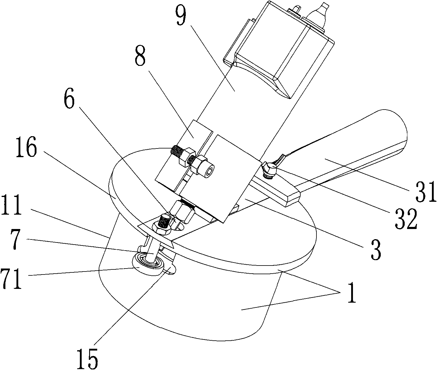
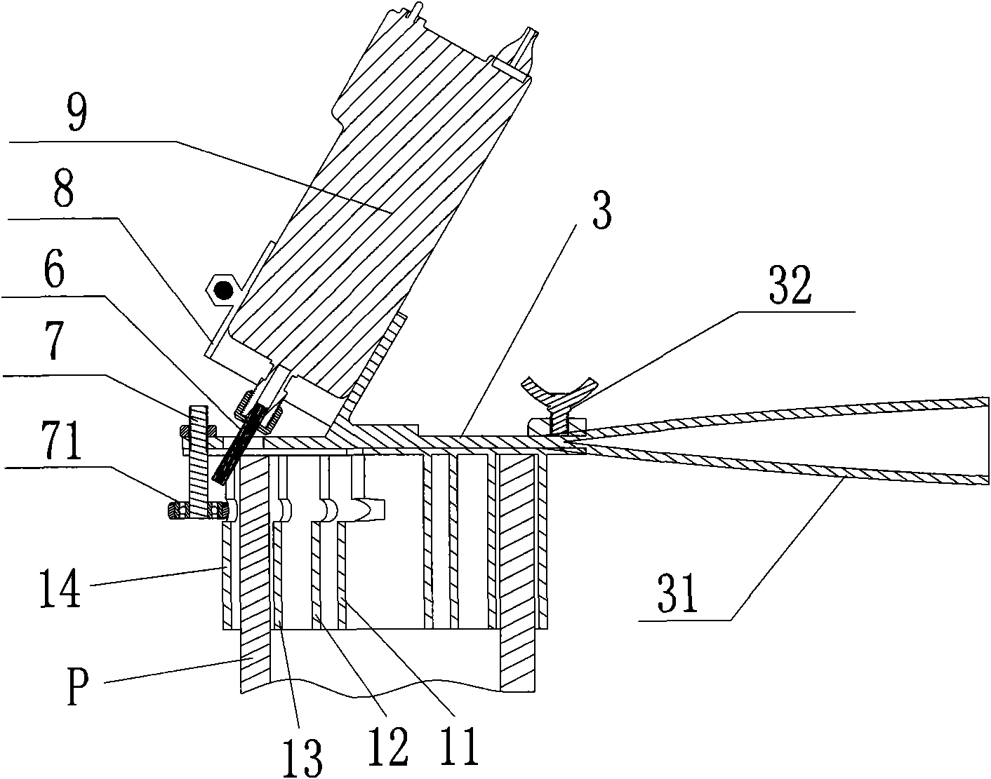
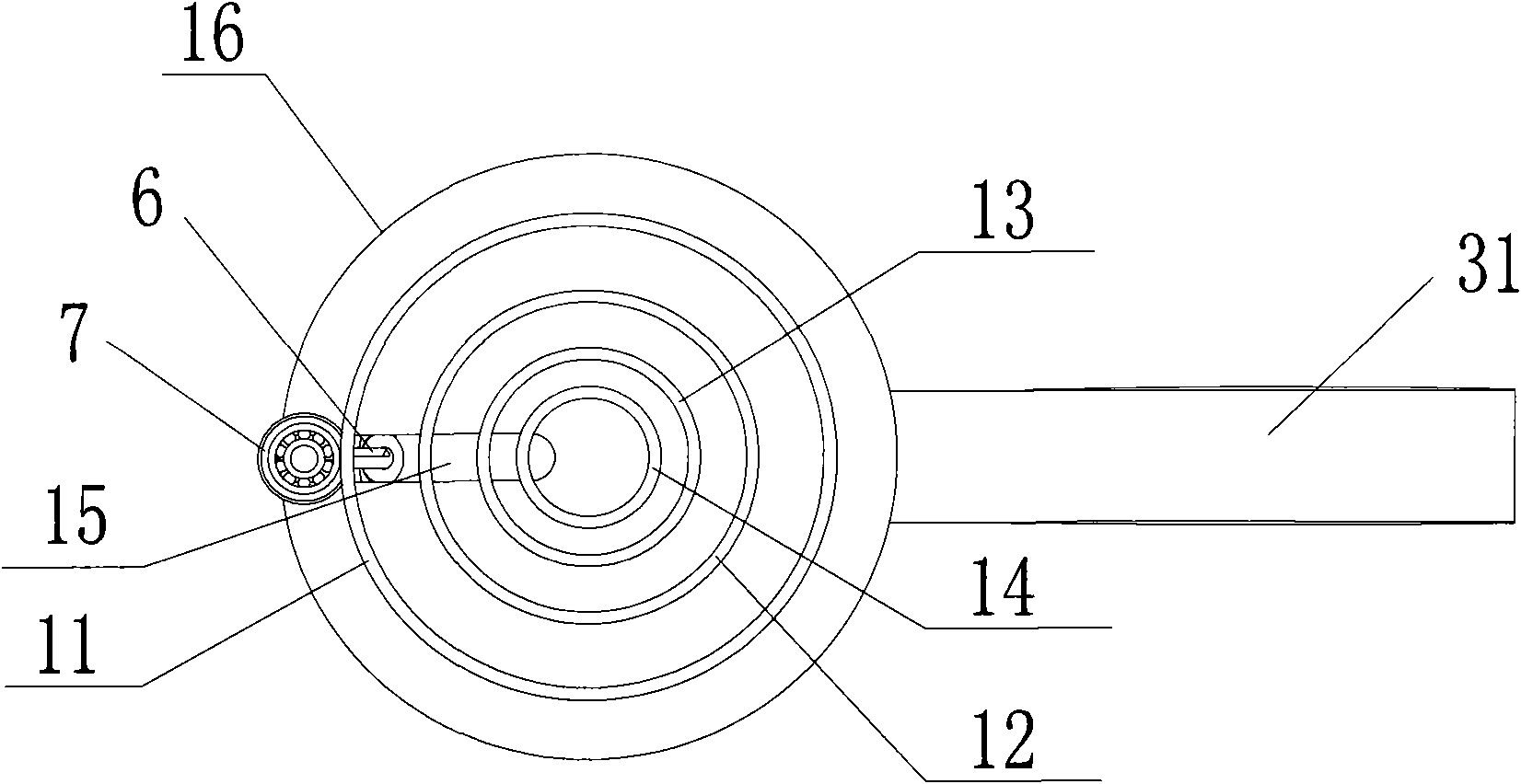
[0022] see Figure 1~3 , the present invention is provided with machine base 8, driving device 9, bevel knife 6, sleeve pipe base 1 and limit lever 7; Driving device 9 is located on the machine base 8, and driving device 9 is provided with motor and transmission part (motor and transmission Not shown in the parts figure), the output shaft of the motor is connected with the transmission part. A slide handle 3 with a handle 31 is provided at the bottom of the frame 8, and a slide groove is provided at the top of the sleeve base 1, and the slide handle 3 is embedded in the slide groove to be slidable. The sliding handle 3 is provided with a sliding handle locking part 32 for positioning the sliding handle 3 . The groove cutter 6 is connected with the transmission part of the driving device, the longitudinal section of the casing seat 1 is T-shaped, the top 16 of the casing seat 1 is disc-shaped, and the bottom of the casing seat 1 is 4 concentric circular tubes. Liner dies 11, ...

Embodiment 2

[0025] Similar to Embodiment 1, the difference is that the bottom of the machine base is connected to the sliding handle via a pivot pin, so that the machine base can rotate around the pin shaft. Therefore, it is easier to adjust the inclination angle of the machine base (that is, the inclination angle of the bevel knife), so as to better meet the bevel requirements of different inclination angles required by the pipe port to be processed.

Embodiment 3

[0027] Similar to Embodiment 1 or 2, the difference lies in that the grip part on the slider is screwed to the body of the slider, so that the slider can be moved by turning the grip part of the slider.


PUM


Abstract

A pipe beveling machine relates to the fabricating machinery of pipes (including delivery pipes and pipeline fittings), which has simple structure, uniform and accurate pipe end inclination, convenient operation, high production efficiency and good safety and is applicable to being used on various pipes on field. The pipe beveling machine is provided with a machine block, a driving device, a bevel cutter, a thimble seat and a stopper; wherein, the driving device is arranged on the machine block and is provided with a motor and a driving part; an output shaft of the motor is connected with the driving part; the bevel cutter is connected with the driving part of the driving device; the thimble seat is connected with the machine block and is provided with liner pipe dies with at least one kind of caliber specification; the liner pipe dies with various caliber specifications share the same axial lead; the bevel cutter is obliquely opposite to the upper end of the liner pipe die; the stopper is arranged on the machine block and is radially opposite to the liner pipe die.

Description

technical field [0001] The invention relates to processing equipment for pipes (including conveying pipes and pipeline fittings), in particular to an electric pipe beveling machine for performing slope forming processing on the ends of pipes. Background technique [0002] In the construction or maintenance of laying pipeline engineering, it is inevitable to encounter situations that require pipe connection. According to the use requirements, it is necessary to make a slope at a certain angle on the end surface of the pipe or pipe fittings for connection and installation. At present, the following methods are generally used to make the end of the pipe into a bevel at a certain angle: [0003] 1. Use a manual steel file to process the slope, and file the end face of the pipe into a slope (slope surface). However, the slope produced by a manual steel file has the disadvantage that the slope of the groove is difficult to grasp , and the production efficiency is low, and the lab...

Claims


Application Information

Patent Timeline
Patent Type & Authority Applications(China)
IPC IPC(8): B23C3/12B23Q3/06
Inventor 陈荣辉
Owner 厦门中井科技有限公司
Learn More