Noise extraction device using microphone
A microphone and noise technology, applied in the direction of frequency/direction characteristic device, microphone signal combination, transducer circuit, etc., to achieve the effect of good vibration resistance
- Summary
- Abstract
- Description
- Claims
- Application Information
AI Technical Summary
Problems solved by technology
Method used
Image
Examples
Embodiment approach 1
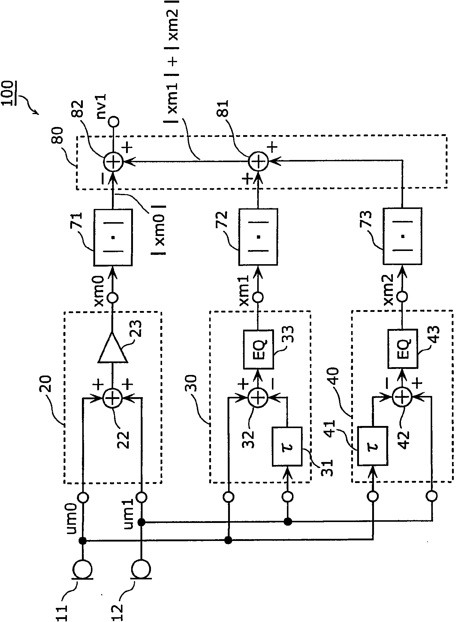
[0077] figure 1 It is a block diagram showing the structure of a noise extraction device using a microphone according to Embodiment 1 of the present invention. In addition, in the following description, the signal in the time zone will be described with the first character of the signal name being a small character, and the signal in the frequency zone will be described with the first character of the signal name being a large character. Note that xm0(n) is denoted as xm0, and Xm0(ω) is denoted as Xm0 for description.
[0078] figure 1 The noise extraction device 100 shown includes a first microphone unit 11 and a second microphone unit 12, and includes a first directivity combining unit 20, a second directivity combining unit 30, a third directivity combining unit 40, and a first signal absolute value. The calculation unit 71, the second signal absolute value calculation unit 72, the third signal absolute value calculation unit 73, and the signal cancellation calculation unit...
Embodiment approach 2
[0155] Hereinafter, Embodiment 2 of the present invention will be described.
[0156] Figure 4 It is a block diagram showing the structure of a noise extraction device using a microphone according to Embodiment 2 of the present invention. For and figure 1 The same elements are given the same reference numerals, and detailed descriptions are omitted.
[0157] Figure 4 The noise extraction device 200 shown includes a first microphone unit 11 and a second microphone unit 12, and includes a first directivity combining unit 20, a second directivity combining unit 30, a third directivity combining unit 40, and a first signal band limiter. Section 61, the second signal band limitation section 62, the third signal band limitation section 63, the first signal absolute value calculation section 71, the second signal absolute value calculation section 72, the third signal absolute value calculation section 73, and the signal cancellation calculation section 80.
[0158] In addition, the...
Embodiment approach 3
[0173] Hereinafter, Embodiment 3 of the present invention will be described.
[0174] Figure 5 It is a block diagram showing the structure of a noise extraction device using a microphone according to Embodiment 3 of the present invention. For and figure 1 and Figure 4 The same parts are assigned the same reference numerals, and detailed descriptions are omitted.
[0175] Figure 5 The noise extraction device 300 shown differs from the noise extraction device 100 of the second embodiment in that the signal restoration unit 90 is provided.
[0176] The signal restoration unit 90 includes a signal sign extraction unit 91 and a signal multiplication unit 92. The signal restoration unit 90 receives the output signal nv1 representing the vibration and noise amplitude information output from the signal cancellation calculation unit 80 and the output signal xm2 from the third directivity combining unit 40, and outputs the output signal nv2.
[0177] Specifically, the signal sign extra...
PUM
 Abstract
Description
Claims
Application Information
 - R&D
- Intellectual Property
- Life Sciences
- Materials
- Tech Scout
- Unparalleled Data Quality
- Higher Quality Content
- 60% Fewer Hallucinations
Browse by: Latest US Patents, China's latest patents, Technical Efficacy Thesaurus, Application Domain, Technology Topic, Popular Technical Reports.
© 2025 PatSnap. All rights reserved.Legal|Privacy policy|Modern Slavery Act Transparency Statement|Sitemap|About US| Contact US: help@patsnap.com


