Eureka AIR delivers breakthrough ideas for toughest innovation challenges, trusted by R&D personnel around the world.

Automatic charging equipment for electric vehicle

An automatic charging device, electric vehicle technology, applied in battery circuit devices, electric vehicles, circuit devices, etc., can solve problems such as affecting the continuation mileage, irregular and reasonable vehicle parking, aging and damage of batteries, etc.

Active Publication Date: 2009-10-28
SUZHOU EAGLE ELECTRIC VEHICLE MFG
View PDF0 Cites 25 Cited by
  • Summary
  • Abstract
  • Description
  • Claims
  • Application Information

AI Technical Summary

Problems solved by technology

However, the current electric locomotive technology is still immature, and there are still some difficult problems to solve in many aspects. Although the current electric locomotives are equipped with rechargeable battery packs as the power source for driving, these rechargeable battery packs are used in electric locomotives. Needs to be recharged after hours of driving
[0003] At present, the charging of the electromechanical battery is to charge the battery in a static state with the matching charger to supplement the power after the battery is discharged. Therefore, it is time-consuming, power-consuming, and labor-intensive. If it is a lead-acid battery, it is even more inconvenient to move it back and forth. , and the battery is charged and discharged in this state, often due to overcharge, undervoltage or overdischarge, the battery is prematurely aged and damaged, which affects the mileage of the continuation
[0004] With the rapid popularization of electric vehicles, the charging of electric vehicles is also extremely important. The simple and fast charging method and the convenience and flexibility in the use of electric vehicles are the goals pursued by people. It is not only cumbersome to operate when charging, but also the wiring is unsafe, and the parking of vehicles is not standardized and reasonable, so there are many deficiencies in charging that need to be improved.

Method used


Image

  • Automatic charging equipment for electric vehicle
  • Automatic charging equipment for electric vehicle

Examples


Embodiment Construction

[0017] The invention designs a fast access parking charging device, which can not only enable the electric vehicle to park safely and reliably for quick access charging, but also enable the electric vehicle to park in a standardized and orderly manner in a community.

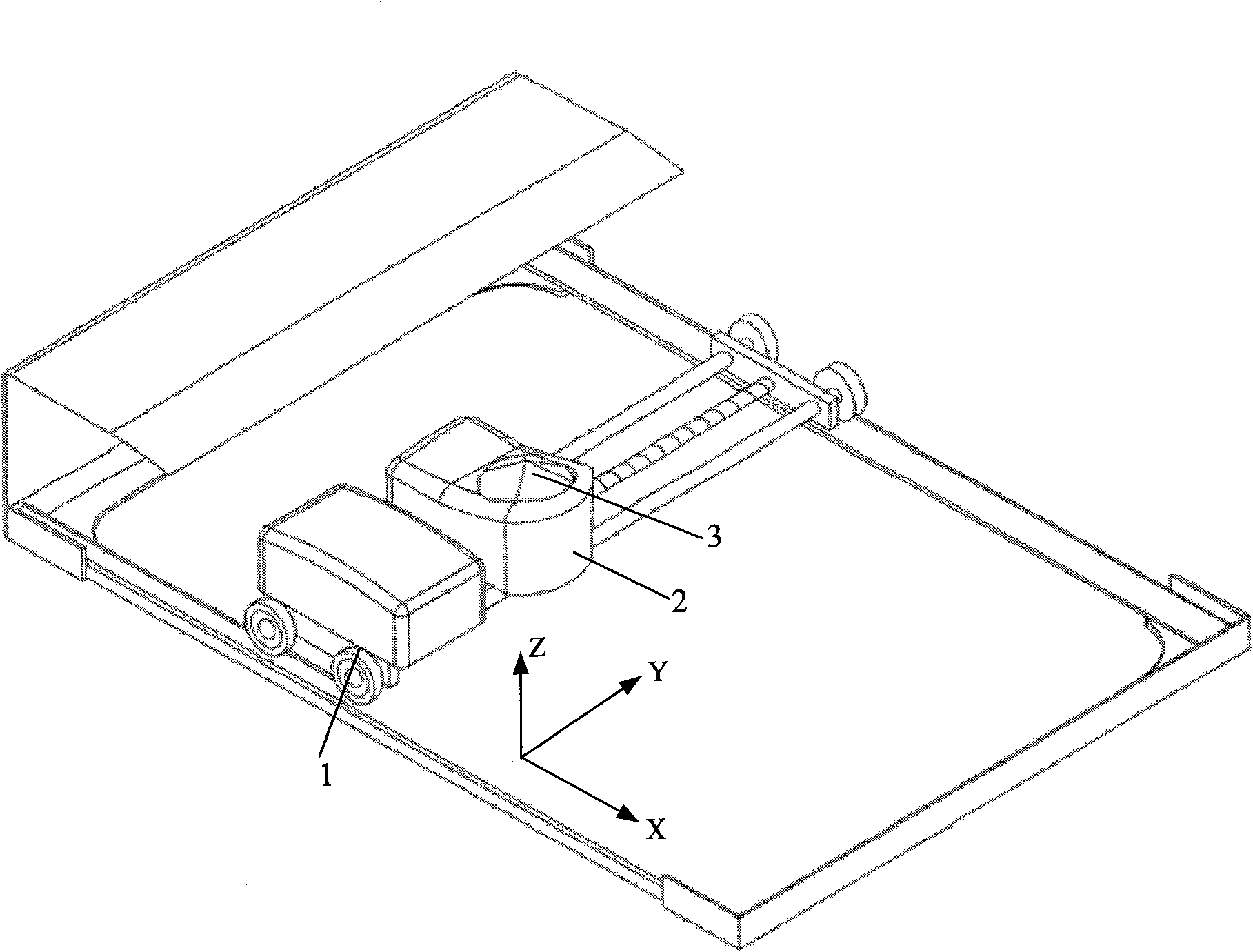
[0018] Such as figure 1 The electric vehicle automatic charging device shown has a mechanical part and an electrical control part, which are divided into a ground system and a vehicle system. The ground system includes mechanical and control devices and charging plugs in three degrees of freedom directions. The three degrees of freedom linkage transmission device includes X Axis transmission unit 1, Y-axis transmission unit 2 and Z-axis transmission unit 3, X-axis transmission unit 1 is perpendicular to Y-axis transmission unit 2, X-axis transmission unit 1 includes an X-axis pulley and a motor that controls the movement of the X-axis pulley, Y The axis transmission unit 2 includes a Y-axis slider and a motor fo...


PUM


Abstract

The invention relates to an automatic charging equipment for an electric vehicle. The ground system includes a three freedom linkage delivery device and a charging plug. The X axis delivery unit comprises an X axis pulley and a motor for controlling the motion of the X axis pulley. The Y axis delivery unit includes a Y axis sliding piece and a motor for controlling the motion of the Y axis sliding piece. The Z axis delivery unit includes a charging plug hoist and a motor for controlling the motion of the charging plug hoist and mounted on the Y axis sliding piece. The Y axis delivery unit is installed on the X axis pulley. A charging plug is mounted on the charging plug hoist. The charging plug is provided with an infrared positioning collection tube and switches in a power box through a contactor. The vehicular system comprises a charging socket and an infrared positioning transmission tube. The charging socket is located on the bottom of the electric vehicle and provided with the infrared positioning transmission tube. The charging socket switches in an accumulator cell via electrical wires. The equipment is utilized in the areas of district, markets and the like and is a convenient and rapid charging mode.

Description

technical field [0001] The invention relates to an automatic charging device for an electric locomotive, belonging to the technical field of charging equipment. Background technique [0002] At present, with the strengthening of people's concept of environmental protection, various electric locomotives powered by electric energy have come out one after another. Compared with motor vehicles powered by gasoline, diesel and other fuels, these electric locomotives will not generate electricity during use. Therefore, it has great environmental protection significance. However, the current electric locomotive technology is still immature, and there are still some difficult problems to solve in many aspects. Although the current electric locomotives are equipped with rechargeable battery packs as the power source for driving, these rechargeable battery packs are used in electric locomotives. Recharging is required after hours of driving. [0003] At present, the charging of the e...

Claims


Application Information

Patent Timeline
IPC IPC(8): H02J7/00G01V8/12B60L11/18
CPCY02T10/7005Y02T10/70
Inventor 张学清朱安定李维平吴国军
Owner SUZHOU EAGLE ELECTRIC VEHICLE MFG
Why Eureka
Eureka Blog
Learn More