
Method and system for reducing frosting degree of air-source heat pump hot water unit in winter

A technology of air source heat pump and water source heat pump units, applied in the field of energy, can solve the problems of compressor intake and exhaust temperature and pressure increase, increase of intake air temperature by about 0.5°C, reduce unit heating capacity, etc., and achieve frosting The effect of reducing the amount of energy, saving defrosting energy consumption, and enhancing reliability and stability

Inactive Publication Date: 2009-10-28
GUANGDONG NEW ENERGY TECH DEV
View PDF0 Cites 12 Cited by
  • Summary
  • Abstract
  • Description
  • Claims
  • Application Information

AI Technical Summary

Problems solved by technology

Someone once proposed to heat the air by relying on the sensible heat discharged from the subcooling of the condensed refrigerant liquid. This method will reduce the heating capacity of the unit, and can only increase the inlet air temperature by about 0.5°C, which cannot meet the requirements at all; in addition, The evaporator will not be frosted during most of the year. When the temperature is high, heating the evaporator inlet air will increase the inlet and outlet temperature and pressure of the compressor, which is not good for the compressor.

Method used


Image

  • Method and system for reducing frosting degree of air-source heat pump hot water unit in winter
  • Method and system for reducing frosting degree of air-source heat pump hot water unit in winter
  • Method and system for reducing frosting degree of air-source heat pump hot water unit in winter

Examples


Embodiment Construction

[0016] The present invention will be further described in detail below in conjunction with the accompanying drawings and embodiments.

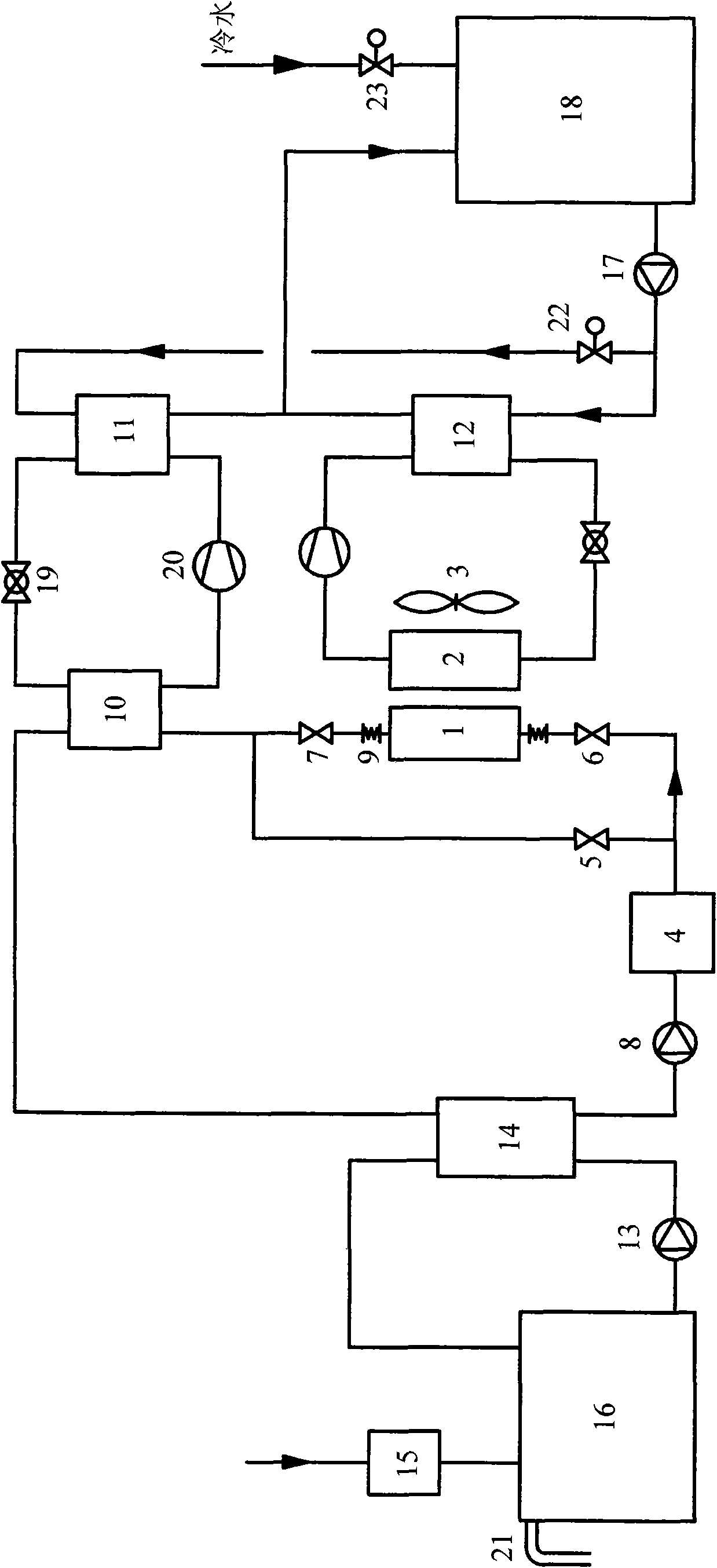
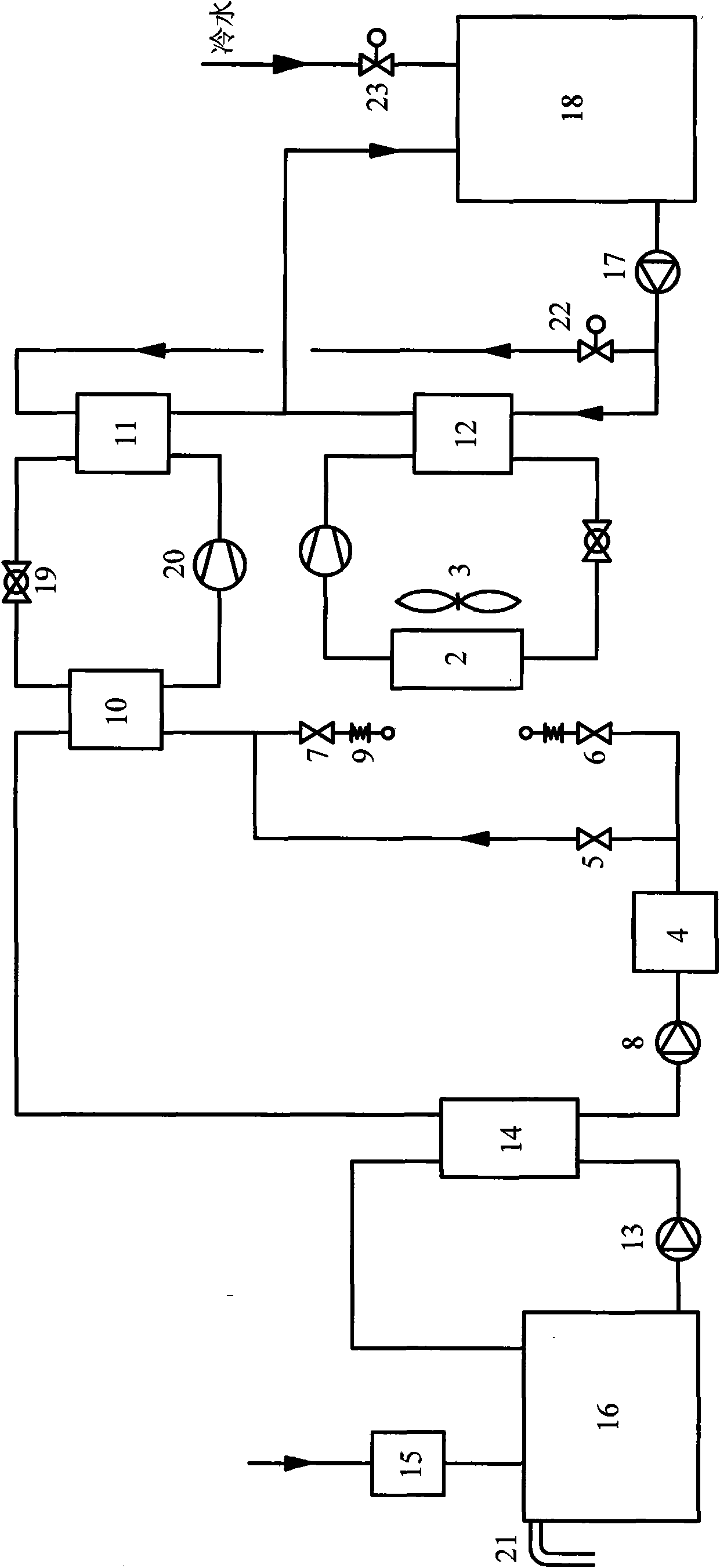
[0017] see figure 1 , the air heater 1 is located on the air intake side of the evaporator 2 of the air source heat pump water heater unit, and both ends are connected to the system through flexible pipes 9 . If multiple air source heat pump water heater units are connected in parallel, multiple air heaters need to be connected in parallel. The fan of the evaporator of the air source heat pump hot water unit is a speed-regulating fan 3, which can be adjusted in two gears. The phase change heat storage device 4, the air heater 1, the evaporator 10 of the water source heat pump unit, the waste water heat exchanger 14 and the intermediate water circulation pump 8 are connected to form an intermediate water circulation loop. The waste water heat exchanger 14, the waste water pump 13 and the waste water tank 16 form a waste water circulation loop...


PUM


Abstract

The invention relates to a waste heat utilizing method and a waste heat utilizing system for reducing the frosting degree of an evaporator of an air-source heat pump hot water unit in winter. In order to overcome the defects in energy dissipation and influence on the system stability, which are existed in the existing defrosting technology, the invention provides a technical proposal as follows: domestic hot water after use is pumped into a waste water heat exchanger and then undergoes heat exchange with medium water in the waste water heat exchanger; the medium water after the heat exchange is pumped into a phase-change heat storage device and then flows into an air heater arranged at the air inlet side of the evaporator of the air-source heat pump hot water unit; the medium water flowing out of the air heater then flows into an evaporator of a water source heat pump unit and then flows back into the waste water heat exchanger. By using the method of heating and warming up the air with the waste hot water, the method and the system improve the temperature of the air entering the evaporator, reduce the relative humidity of the air, greatly reduce the frosting possibility, not only save the energy consumed for defrosting, but also increase the heat supply of the unit and enhance the reliability and the stability of operation of the system.

Description

technical field [0001] The invention belongs to the field of energy technology, and in particular relates to a waste heat utilization method and system capable of reducing the frosting amount of an evaporator of an air source heat pump hot water unit in winter. Background technique [0002] The air source heat pump hot water unit absorbs low-grade heat energy in the surrounding air through the heat pump cycle to produce domestic hot water. It has the advantages of energy saving, safety, environmental protection, and less floor space. It is a hot water supply that has boomed in recent years. The method has been applied in quite a few hot water supply projects. However, the heating capacity of the air source heat pump water heater unit decreases rapidly with the decrease of the temperature. When the temperature in winter drops to a certain level and the surface temperature of the evaporator is lower than 0°C and lower than the dew point temperature of the air, the evaporator ...

Claims


Application Information

Patent Timeline
Patent Type & Authority Applications(China)
IPC IPC(8): F25B47/00F28D20/00F25B30/06
CPCY02E60/142Y02E60/14
Inventor 陈晓
Owner GUANGDONG NEW ENERGY TECH DEV
Learn More