
Apparatus and method for non-contacting blade oscillation measurement

A vibration measurement, non-contact technology, used in measurement devices, vibration measurement in solids, measurement of vibration and other directions, can solve problems such as interference and measurement data errors, and achieve the effect of improving amplitude resolution

Inactive Publication Date: 2009-10-21
MTU AERO ENGINES GMBH
View PDF0 Cites 30 Cited by
  • Summary
  • Abstract
  • Description
  • Claims
  • Application Information

AI Technical Summary

Problems solved by technology

In this way, it is true that the influence on the angular position of the detector in the resonance range of constant offset can be largely eliminated, but if there is a sudden change in the rotor orientation or the housing shape of the drive device in resonance, for example due to the opening of the purge valve or As can happen if the switch is turned off, it will cause interference, or errors in the measured data

Method used


Image

  • Apparatus and method for non-contacting blade oscillation measurement
  • Apparatus and method for non-contacting blade oscillation measurement

Examples


Embodiment Construction

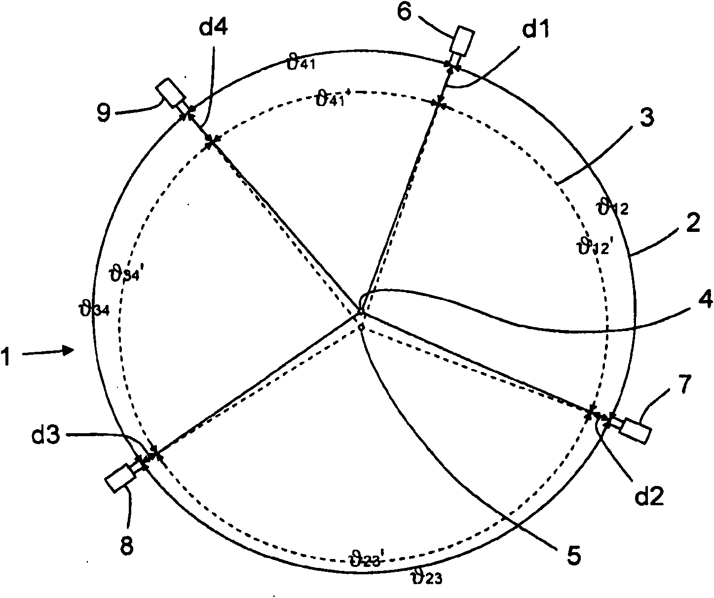
[0029] figure 1 The schematic cross-sectional view shown shows the correction of the effective detector position by an integrated radial gap analysis according to the invention in non-contact blade vibration measurement (BSSM).

[0030] Here, four capacitive sensors 6 , 7 , 8 , 9 are arranged distributed on the circumference of the compressor housing 2 . The mounting of the sensors 6 , 7 , 8 , 9 takes place, for example, by screwing them into corresponding threaded holes on the outer shell of the housing.

[0031] In addition, in figure 1 The housing axis 4 and the rotor axis 5 in the center of the compressor housing 2 are also shown in . The two axes 4 , 5 are not aligned in the present embodiment, but are offset from each other. The circumference of the rotor 3 equipped with rotor blades is indicated by the circle drawn with dotted lines in the housing 2 .

[0032]Among them, the first sensor 6 is used to measure the gap d1 between the housing inner wall of the housing 2...


PUM


Abstract

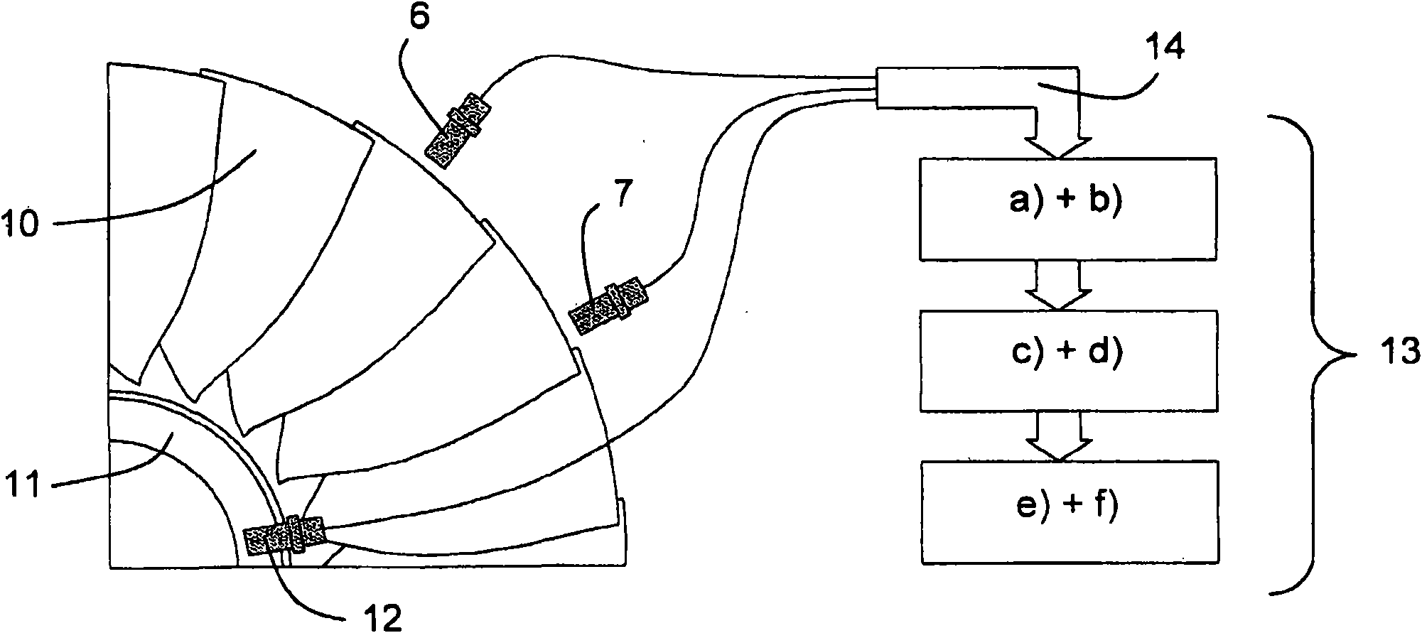
An apparatus for non-contacting blade oscillation measurement having sensors (6, 7, 8, 9) which are arranged around the circumference of a rotor (3) which is formed with rotor blades (10), having a signal detection unit (14) and having an evaluation unit (13), is characterized in that devices are provided to determine the rotor position and / or the housing deformation. Furthermore, a method is specified for non-contacting blade oscillation measurement. This avoids the technical problems of the prior art and provides a better apparatus and a better method for non-contacting blade oscillation measurement. In particular, the solution according to the invention eliminates the effect of rotor radial movements and housing deformation, that is to say oval deformation, on the measurement data, in this way ensuring good amplitude resolution for the oscillation analysis, in all conditions.

Description

technical field [0001] The invention relates to a device for non-contact blade vibration measurement, which includes: sensors arranged around the circumference of a rotor designed with working blades, a signal acquisition unit and an analysis and processing unit; the invention also relates to a device with A method for non-contact blade vibration measurement. Background technique [0002] In principle, the non-contact blade vibration measurement (BSSM) of the working blades of the axial air compressors of aeronautical drive gas turbines or stationary industrial gas turbines is known from the prior art, which is commonly referred to internationally as blade vibration measurement (BSSM). Terminal timing (Tip-Timing). This measurement is required because during operation there are high static aerodynamic and alternating aerodynamic effects on the blade which can excite the blade to vibrate. Additionally, blade vibrations may be caused by pressure distribution in the airflow b...

Claims


Application Information

Patent Timeline
Patent Type & Authority Applications(China)
IPC IPC(8): G01H1/00
CPCG01H1/006
Inventor M·杰林斯基G·齐勒尔
Owner MTU AERO ENGINES GMBH
Learn More