
A crankshaft bearing arrangement of a combustion engine

A technology of crankshaft bearings and bearing devices, which is applied in the direction of crankshaft bearings, shafts and bearings, ball bearings, etc., can solve the problems of expensive production and achieve long service life and light cost-effective effects

Inactive Publication Date: 2012-07-18
HUSQVARNA AB
View PDF6 Cites 0 Cited by
  • Summary
  • Abstract
  • Description
  • Claims
  • Application Information

AI Technical Summary

Problems solved by technology

[0007] Also, this solution is rather expensive to produce, since an expensive rubber has to be used to coat the rubberized periphery

Method used


Image

  • A crankshaft bearing arrangement of a combustion engine
  • A crankshaft bearing arrangement of a combustion engine
  • A crankshaft bearing arrangement of a combustion engine

Examples


Embodiment Construction

[0026] The invention will be described more fully hereinafter with reference to the accompanying drawings, in which preferred embodiments of the invention are shown. However, this invention may be embodied in many different forms and should not be construed as limited to the embodiments set forth herein; rather, these embodiments are provided so that this disclosure will be thorough and complete, and will The scope of the invention is fully conveyed to those skilled in the art. In the figures, the same reference numerals designate the same parts.

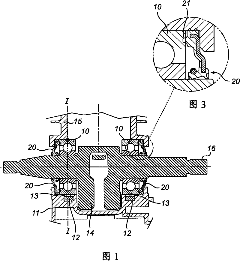
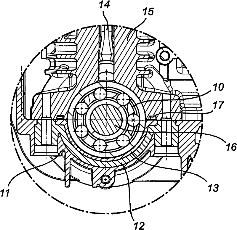
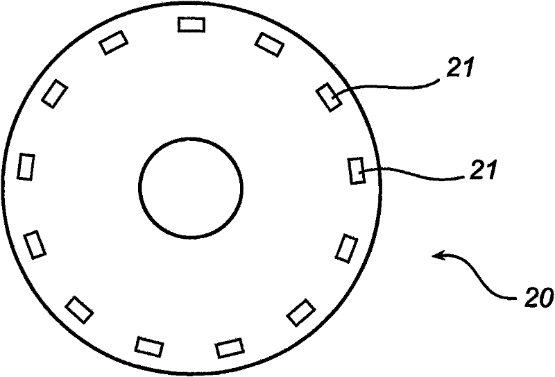
[0027] In the embodiment of the invention described in the drawings a crankshaft 16 is shown, journaled in two bearings 10 in the form of ball bearings. However, other types of bearings can also be used. Located between the two bearings 10 and mounted on the crankshaft is a crankshaft assembly 14 having piston rods and counterweights. The bearing 10 is inserted in a bearing block which in this embodiment comprises an upper part 1...


PUM


Abstract

The present invention refers to a crankshaft bearing arrangement for an internal combustion engine. The bearing arrangement comprises: a bearing (10) arranged at a crankshaft (16) of an internal combustion engine; a bearing seat (11, 15) for housing the bearing (10); and a sealing arrangement (20) for sealing against the crankshaft (16) and the bearing seat (11, 15) . The at least one part of thebearing seat (11) has a reinforcement (12) arranged in the bearing seat, and a surface (13) of the at least one part of the bearing seat (11), which surface (13) bears against the bearing (10), is made from a plastic material.

Description

technical field [0001] The present disclosure relates to a crankshaft bearing arrangement of an internal combustion engine, and more particularly to a crankshaft bearing arrangement of an internal combustion engine of a hand-held motor-driven tool. Background technique [0002] In the development of internal combustion engines for motor-driven tools such as chainsaws, hedge trimmers, lawnmowers, etc., bearing sleeves have been used to eliminate the need to post-process the housings of the crankshaft bearings after their manufacture. [0003] In US4974973 and WO97 / 45649, it has been recorded that the crankshaft bearing device adopts this bearing sleeve. In a bearing arrangement such as US4974973, the bearing may be provided in a bearing sleeve formed as a tin cup with a rubber-coated outer circumference. This rubberized periphery is arranged to compensate for tolerances (eg dimensional variations in the production of eg bearing housings) and to seal the cylinder and crankcas...

Claims


Application Information

Patent Timeline
Patent Type & Authority Patents(China)
IPC IPC(8): F16C9/02
CPCF02F7/0053F16C9/02F16C33/7886F16C2360/22F16C19/06
Inventor 彼得·比约克曼马茨·格兰斯泰特
Owner HUSQVARNA AB
Learn More