
Analytical method of rotor transient signal

A transient signal analysis and rotor technology, applied to measuring devices, instruments, measuring ultrasonic/sonic/infrasonic waves, etc., can solve problems such as unbalance, low resolution, incomplete extraction signals, etc.

Active Publication Date: 2009-10-21
郑州恩普特科技股份有限公司
View PDF3 Cites 15 Cited by
  • Summary
  • Abstract
  • Description
  • Claims
  • Application Information

AI Technical Summary

Problems solved by technology

At present, the methods used for transient signal analysis mainly include tracking axis trajectory method, Bode diagram method, polar coordinate diagram method, three-dimensional spectral array method, Campbell diagram method, etc. These methods are very important for understanding the inherent characteristics of the system, mass imbalance distribution, fault analysis and diagnosis provide a very effective means, but in these methods except the tracking axis trajectory method, the rest are analysis techniques based on single-channel signals, which generally have the disadvantage of incomplete signal extraction. Although the tracking axis trajectory method uses the signals of two channels, it has the disadvantages of low resolution, and the existing transient signal analysis methods cannot fully meet the needs of the site.

Method used


Image

  • Analytical method of rotor transient signal
  • Analytical method of rotor transient signal
  • Analytical method of rotor transient signal

Examples


Embodiment Construction

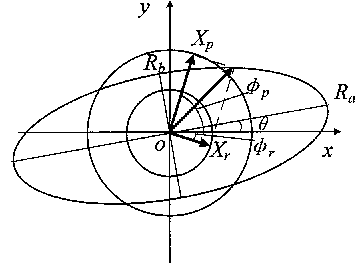
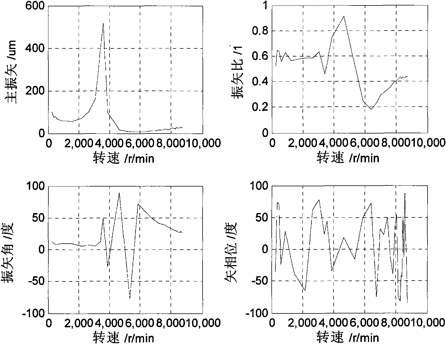
[0026] The full vector diagram actually includes four diagrams, namely, the main vibration vector diagram, the vibration vector ratio diagram, the vibration vector angle diagram, and the vector phase diagram. The following takes the vibration of a single frequency as an example to illustrate the physical meaning of each parameter.

[0027] Suppose the motion equation of the center of the disk rotating at Ω angular velocity can be expressed as:

[0028]

[0029] In the formula, X, Y, are the amplitude and initial phase angle in the x and y directions, respectively.

[0030] The running track of the center of the disc represented by formula (1) is an ellipse. The parameters of the full vector spectrum are related to X, Y, The relationship between them can be expressed as formula (2)

[0031]

[0032] In the formula, V m is the main vibration vector, V s is the auxiliary vibration vector, ρ is the vibration vector ratio, θ is the vibration vector angle, φ α is the v...


PUM


Abstract

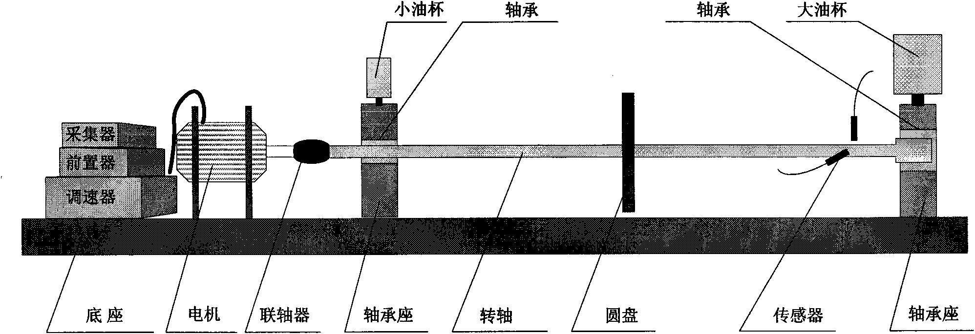
The invention discloses an analytical method of a rotor transient signal, which comprises the following steps: 1) two orthogonal current vortex displacement sensors are arranged on a rotor section to collect a vibration signal of a rotor relative to a bearing support, the direction of the sensor from X to Y is consistent with the rotation direction of the rotor, and an equal rotary speed signal is adopted for collection and a key phase signal is used for simultaneous complete alternation sampling; 2) signals collected are processed with anti-alias filtering, low-pass filtering and the like to remove unnecessary interference noise signals; 3) the computation of main vibration vector, vibration vector ratio, vibration vector angle and vector phase is conducted, complex FFT conversion is adopted and one-time FFT computation is utilized to obtain such characteristic parameters; 4) a relational graph of each parameter relative to rotation speed or other variables is drawn; and 5) a main vibration vector graph is used for expressing the vibration strength change of measuring points under a single frequency, a vibration vector ratio graph is used for expressing the ovality change of the single frequency vortex track of measuring points, a vibration vector angle graph is used for expressing the change of maximum vibrating direction, and a vector phase graph is used for expressing the change of a vibration vector and a reference phase point.

Description

technical field [0001] The invention relates to transient signal analysis for rotating machinery, and can be extended to fault diagnosis of rotating machinery. Background technique [0002] On-line monitoring technology of rotating machinery is one of the important means to understand the operating status of equipment and ensure the safe operation of equipment. Among them, the collection and analysis of transient data such as startup and shutdown of rotating machinery is one of the effective means to fully understand the operating status of equipment. At present, the methods used for transient signal analysis mainly include tracking axis trajectory method, Bode diagram method, polar coordinate diagram method, three-dimensional spectral array method, Campbell diagram method, etc. These methods are very useful for understanding the inherent characteristics of the system, mass imbalance distribution, fault analysis and diagnosis provide a very effective means, but in addition ...

Claims


Application Information

Patent Timeline
IPC IPC(8): G01H11/06G01M13/00
Inventor 陈宏韩捷董辛旻郝伟
Owner 郑州恩普特科技股份有限公司
Learn More