
Large vacuum coating equipment

A vacuum coating, large-scale technology, applied in the direction of vacuum evaporation coating, sputtering coating, gaseous chemical coating, etc., can solve the problems of affecting product quality, loss of pumping function, high production cost, etc., to save pumping energy consumption , shorten the time of rough pumping and save the cost of equipment

Inactive Publication Date: 2009-10-21
SHENZHEN UNIV
View PDF0 Cites 10 Cited by
  • Summary
  • Abstract
  • Description
  • Claims
  • Application Information

AI Technical Summary

Problems solved by technology

However, the former has high energy consumption and serious oil vapor pollution, which affects product quality; the latter is expensive, and the adsorption surface (composed of activated carbon at -258°C) is easily polluted and poisoned, loses the function of pumping, and has high maintenance costs
[0003] In addition, these two pumps can only work at a pressure lower than 1 Pa, and the rough pump can only pump the large coating chamber to tens of Pa. Therefore, the coating equipment needs to be equipped with high energy consumption and large oil vapor pollution. Roots pump
[0004] Therefore, traditional large-scale vacuum coating equipment usually uses oil diffusion pumps and Roots pump units to pump air, resulting in high production costs and poor product quality, which has become a major problem in the current vacuum coating industry.

Method used


Image

  • Large vacuum coating equipment
  • Large vacuum coating equipment

Examples


Embodiment 1

[0029] Embodiment 1. Large-scale single-chamber vacuum coating equipment

[0030] This example figure 1 As shown, one side of the coating chamber 11 communicates with the water vapor pump 12, and the water vapor pump 12 communicates with the dragging molecular pump 14 through a high vacuum valve 13, and the dragging molecular pump 14 communicates with the dragging molecular pump 14 through a vacuum valve 18. The backing pump 17 is in communication; the water vapor pump 12 is also in communication with the rough pump 16 through a low vacuum valve 15 .

[0031] This embodiment has the following advantages:

[0032] (1) In this embodiment, the traction molecular pump 14 and the water vapor pump 12 are used to replace the oil diffusion pump and Roots pump of the traditional coating equipment, so as to save 80% of energy consumption for pumping, improve the efficiency of vacuum coating, and improve the quality of coating products.

[0033] (2) The water vapor pump 12 does not nee...

Embodiment 2

[0038] Embodiment 2. Large-scale vacuum coating equipment using a built-in water vapor pump

[0039] The basic structure of this embodiment is the same as that of Embodiment 1, the difference is that the water vapor pump is directly installed in the coating chamber, which saves equipment costs and occupied space, and improves the effective pumping speed of the water vapor pump.

Embodiment 3

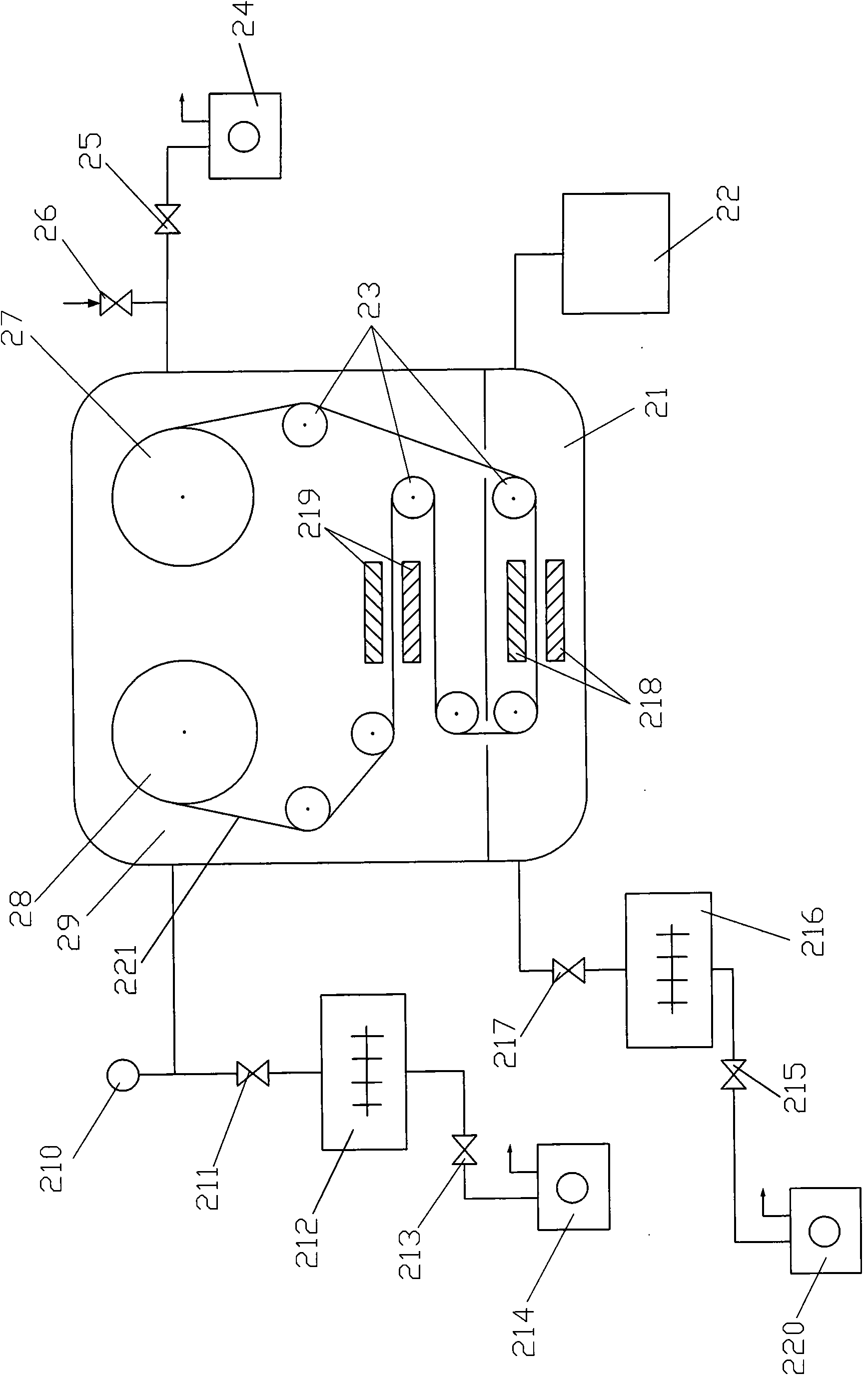
[0040] Embodiment 3. Double-chamber winding large-scale vacuum coating equipment

[0041] This example figure 2 As shown, the coating equipment is composed of a winding chamber 29 and a coating chamber 21; one end of the winding chamber 29 communicates with the drag molecular pump 212 through a vacuum valve 211, and the drag molecular pump 212 communicates with the drag molecular pump 213 through a vacuum valve 213. The backing pump 214 communicates; the other end of the winding chamber 29 communicates with the rough pump 24 through a vacuum valve 25; the coating chamber 21 communicates with another traction molecular pump 216 through a vacuum valve 217, the traction The molecular pump 216 communicates with another backing pump 220 through a vacuum valve 215; the other end of the coating chamber 21 directly communicates with the water vapor pump 22; the coating chamber 21 is provided with a magnetron sputtering target 218.

[0042] In addition, the winding chamber 29 is also...


PUM


Abstract

The invention relates to a large vacuum coating equipment. A combined unit of a large pumping speed molecular drag pump and a water vapor pump is adopted to replace a diffusion pump and a lobed element pump of the traditional large vacuum coating equipment. The large vacuum coating equipment can save the air exhaust energy consumption by 80 percent, shortens rough pumping time, greatly reduces oil vapor pollution of a coating chamber and obviously improves the quality of coating products; a set of rough pumping system can be shared by a plurality of coating equipment, thus saving equipment cost and occupied space.

Description

technical field [0001] The invention belongs to the field of vacuum coating, in particular to a large-scale vacuum coating equipment. Background technique [0002] Large-scale vacuum coating equipment has a large volume (usually up to several cubic meters), a short coating cycle (usually about 30 minutes), and a high background vacuum (usually 10 -3 ~10 -2 Pa), plus the inner wall of the coating chamber and the parts to be coated (especially plastic parts to be coated) will emit a large amount of gas (of which condensable gas usually accounts for 90%), so the equipment usually needs to be equipped with 10,000 to tens of thousands of L / s large high vacuum pump. Among traditional vacuum pumps, the only high vacuum pumps that can meet the above requirements are oil diffusion pumps and cryogenic pumps. However, the former has high energy consumption and serious oil vapor pollution, which affects product quality; the latter is expensive, and the adsorption surface (composed o...

Claims


Application Information

Patent Timeline
Patent Type & Authority Applications(China)
IPC IPC(8): C23C14/56C23C14/35C23C16/54
Inventor 储继国龚建华
Owner SHENZHEN UNIV
Learn More