Improved structure of combined type plane cutter
A combination, planer technology, applied in the direction of rotary cutting tools, wood processing equipment, manufacturing tools, etc., to prevent the knife part from flying off and ensure the effect of accuracy
- Summary
- Abstract
- Description
- Claims
- Application Information
AI Technical Summary
Problems solved by technology
Method used
Image

Examples
Embodiment 1
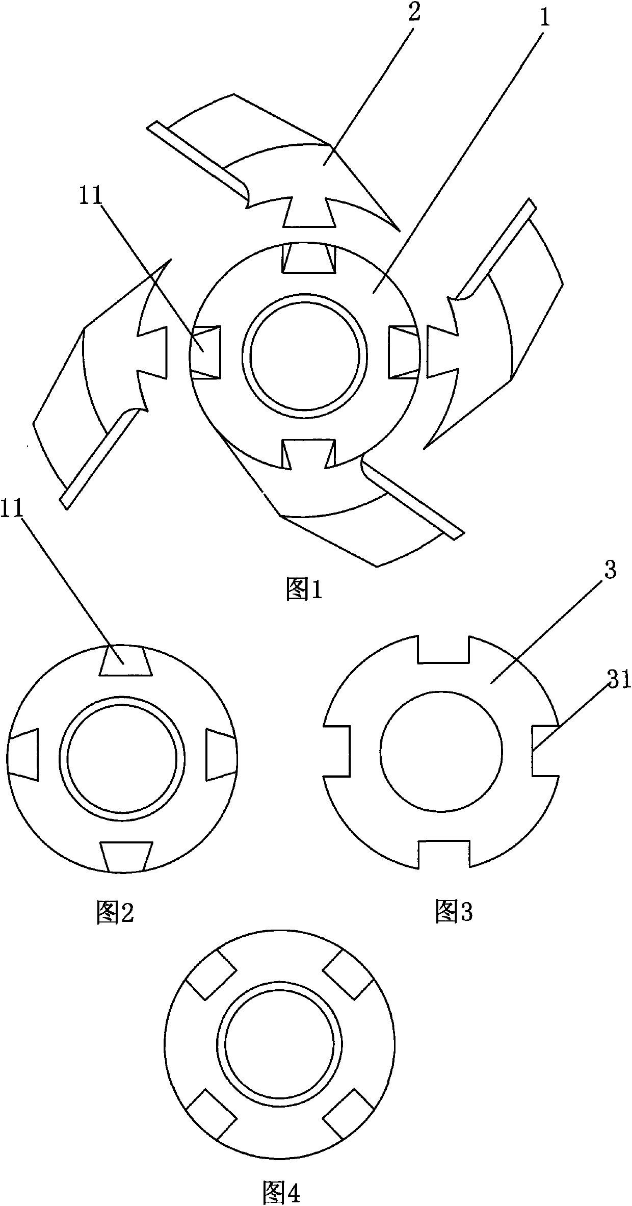
[0022] like Figure 1-Figure 4 As shown, the present invention includes a shaft sleeve 1 and a plurality of knife parts 2 rings arranged on the shaft sleeve 1, a dovetail groove 11 is provided on the shaft sleeve 1, and the handle of the knife part is adapted to the dovetail groove 11. , the shaft sleeve 1 is provided with a limit mechanism to prevent the knife part 2 from sliding, the limit mechanism includes a rotating plate 3 sleeved on the shaft sleeve, and a chute 31 is opened on the edge of the rotating plate 3; the knife portion After passing through the chute 31, it is flexibly connected with the shaft sleeve, and the rotating plate 3 is rotated so that the chute 31 and the dovetail groove 11 are staggered and arranged.
[0023] When installing, the knife part 2 is clamped in the dovetail groove 11 after passing through the chute 31, and then the rotating plate 3 is rotated so that the chute 31 on the rotating plate 3 is staggered from the dovetail groove 11 on the bus...
Embodiment 2
[0025] like Figure 7-Figure 8 As shown, the present invention includes a shaft sleeve 1 and a plurality of knife parts 2 rings arranged on the shaft sleeve 1, a dovetail groove 11 is provided on the shaft sleeve 1, and the handle of the knife part is adapted to the dovetail groove 11. , the bushing 1 is provided with a limit mechanism to prevent the knife part 2 from sliding, the limit mechanism includes a baffle plate 4, the edge of the baffle plate 4 is provided with a chute 2 5, and the chute 2 5 and the dovetail groove 11 are staggered and set , a pagoda spring 6 is connected on the baffle plate 4, and one end of the pagoda spring 6 is fixed on the shaft sleeve 1, a bump 12 is set on the shaft sleeve, and a block corresponding to the bump 12 is provided on the baffle plate 4 Groove 41 , the protrusion 12 passes through the blocking groove 41 .
[0026] During installation, the chute 2 5 on the baffle plate 4 is turned to the dovetail groove 11 on the shaft sleeve, and th...
Embodiment 3
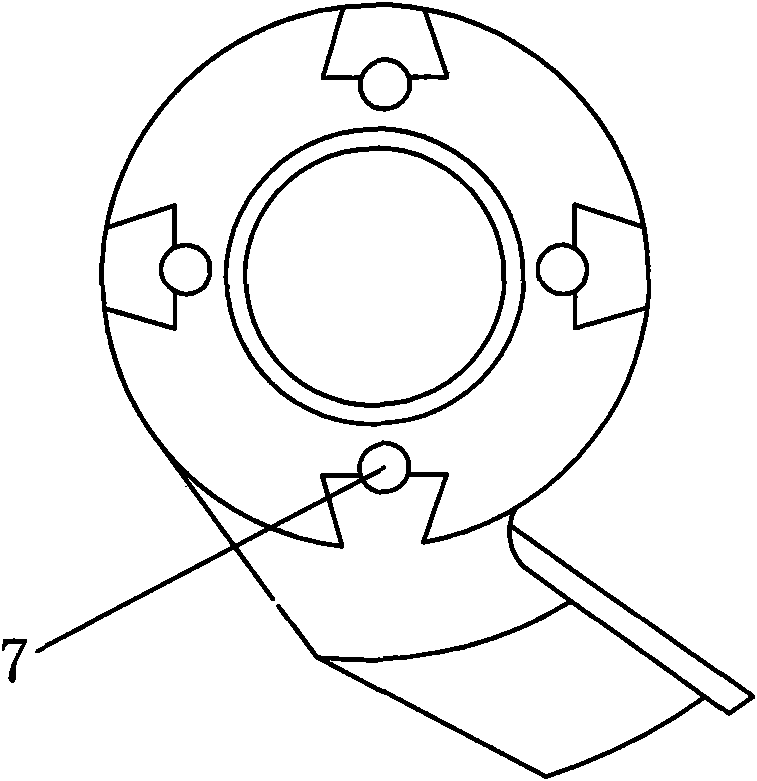
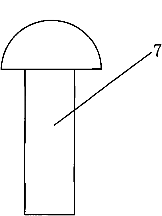
[0028] like Figure 5-Figure 6 As shown, the present invention includes a shaft sleeve 1 and a plurality of knife parts 2 rings arranged on the shaft sleeve 1, a dovetail groove 11 is provided on the shaft sleeve 1, and the handle of the knife part is adapted to the dovetail groove 11. , The shaft sleeve 1 is provided with a limit mechanism to prevent the knife portion 2 from sliding, the limit mechanism includes a bolt 7, and the bolt 7 is threadedly connected with the shaft sleeve 1. Simple bolts are used, and the head of the bolt bears against the knife part, thereby forming a limit on the knife part 2.
PUM
 Abstract
Description
Claims
Application Information
 - R&D
- Intellectual Property
- Life Sciences
- Materials
- Tech Scout
- Unparalleled Data Quality
- Higher Quality Content
- 60% Fewer Hallucinations
Browse by: Latest US Patents, China's latest patents, Technical Efficacy Thesaurus, Application Domain, Technology Topic, Popular Technical Reports.
© 2025 PatSnap. All rights reserved.Legal|Privacy policy|Modern Slavery Act Transparency Statement|Sitemap|About US| Contact US: help@patsnap.com