Liquid crystal display drive circuit

A liquid crystal display and drive circuit technology, applied to static indicators, instruments, etc., can solve problems such as incomplete display, insufficient humanization of products, and failure of drive circuits to work normally, and achieve the effect of strong humanization

Active Publication Date: 2009-10-14
K TRONICS (SUZHOU) TECH CO LTD +1
View PDF0 Cites 8 Cited by
  • Summary
  • Abstract
  • Description
  • Claims
  • Application Information

AI Technical Summary

Problems solved by technology

[0004] When the power is turned off, that is, when VDD is powered off, DVDD, AVDD, VON, and VOFF will all become zero within a few milliseconds. During this process, the drive circuit cannot work normally, and the gate cannot be completely turned off or on. As a result, the display of one frame of the picture cannot be completed, resulting in obvious horizontal bright blocks appearing on the picture, and then gradually disappearing, resulting in bad visual effects
[0005] Therefore, it can be seen that the liquid crystal display in the prior art cannot perform intelligent processing when the power is off, and give the user a corresponding prompt, and the humanization of the product is insufficient.

Method used


Image

  • Liquid crystal display drive circuit
  • Liquid crystal display drive circuit
  • Liquid crystal display drive circuit

Examples


Embodiment 1

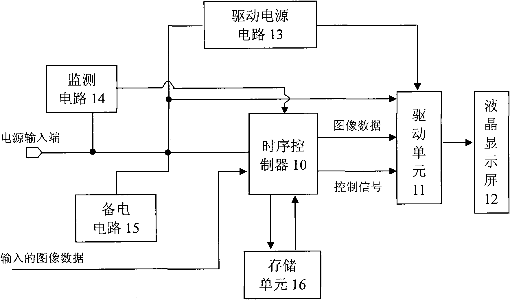
[0023] Such as figure 2 As shown, the liquid crystal display driving circuit of this embodiment includes a timing controller 10 connected to the input terminal of the power supply, the output terminal of the timing controller 10 is connected to the driving unit 11, and the output terminal of the driving unit 11 is connected to the liquid crystal display screen 12; wherein, the power input end is also connected with a drive power circuit 13, and the output end of the drive power circuit 13 is connected to the drive unit 11; the power input end is also connected with a monitoring circuit 14, and the monitoring The output end of circuit 14 is connected to described timing controller 10; The input end of described timing controller 10, driving power supply circuit 13 and drive unit 11 is also connected with backup power circuit 15; Described timing controller 10 is also connected with storage Unit 16 is used for storing the data of the power-off prompt screen.

[0024] During no...

Embodiment 2

[0039] It is generally the same as Embodiment 1, except that the liquid crystal display driving circuit of this embodiment is further provided with a backlight source monitoring circuit 18 .

[0040] Such as Figure 5 As shown, the backlight monitoring circuit 18 includes a third reset chip, the ground terminal of the third reset chip is grounded, and the input terminal is connected to the backlight power signal terminal of the liquid crystal display 12 (ie Figure 5 In B / L Vddin), the output end is connected to the timing controller, and at the same time, it is also connected to the resistor R5 and then grounded; the connection line between the output end of the third reset chip and the timing controller is also connected to the third reset chip through the resistor R4 input terminal. Resistors R4 and R5 can realize voltage division of the backlight power supply, which is convenient for monitoring by the third reset chip. If the third reset chip detects that the divided bac...


PUM


Abstract

The invention discloses a liquid crystal display drive circuit which belongs to the technical field of liquid crystal displays and is designed to solve the problems that the prior liquid crystal displays can not supply corresponding promotions for users during power failure and are not quite humanized. The liquid crystal display drive circuit comprises a time schedule controller connected with the input end of a power source, the output end of the time schedule controller is connected with a drive unit, and the output end of the drive unit is connected to the liquid crystal display, wherein the input end of the power source is also connected with a driving power supply circuit and a monitoring circuit, the output end of the driving power supply circuit is connected to the drive unit, and the output end of the monitoring circuit is connected to the time schedule controller; the input ends of the time schedule controller, the driving power supply circuit and the drive unit are also connected with an auxiliary power supply circuit; and the time schedule controller is also connected with a storage unit used for storing power-fail promoting picture data. The invention is suitable for the liquid crystal displays.

Description

technical field [0001] The invention relates to a liquid crystal display, in particular to a driving circuit of a liquid crystal display. Background technique [0002] When the liquid crystal display is powered off, due to the fast power-off speed, the driving circuit cannot complete the driving display of one frame of the picture, and cannot give the user a prompt, so the current circuit is simply turned off directly. In a typical driving circuit, the driving The power circuit part such as figure 1 shown. Among them, VDD is the input voltage of the driving power supply circuit, usually 5V; VDD is also the input voltage of the timing controller and Driver IC (driver unit) in the driving circuit (omitted in this part of the circuit); VON is the gate open voltage of the pixel; VOFF is the gate turn-off voltage of the pixel; AVDD is the driving voltage of each gray level and VCOM (reference voltage circuit), and the parts of each gray level and VCOM are also omitted in this c...

Claims


Application Information

Patent Timeline
IPC IPC(8): G09G3/36G09G3/34
Inventor 肖向春
Owner K TRONICS (SUZHOU) TECH CO LTD
Why Eureka
Try Eureka