A connector sealing element

A technology of seals and connectors, which is applied in the direction of connections, components of connection devices, electrical components, etc., and can solve problems such as inability to detect holes 68

Active Publication Date: 2009-10-07
YAZAKI CORP
View PDF1 Cites 9 Cited by
  • Summary
  • Abstract
  • Description
  • Claims
  • Application Information

AI Technical Summary

Problems solved by technology

A test pin or air leak test therefore cannot detect the presence of hole 68, resulting in water being able to enter the connector during use

Method used


Image

  • A connector sealing element
  • A connector sealing element
  • A connector sealing element

Examples


Embodiment Construction

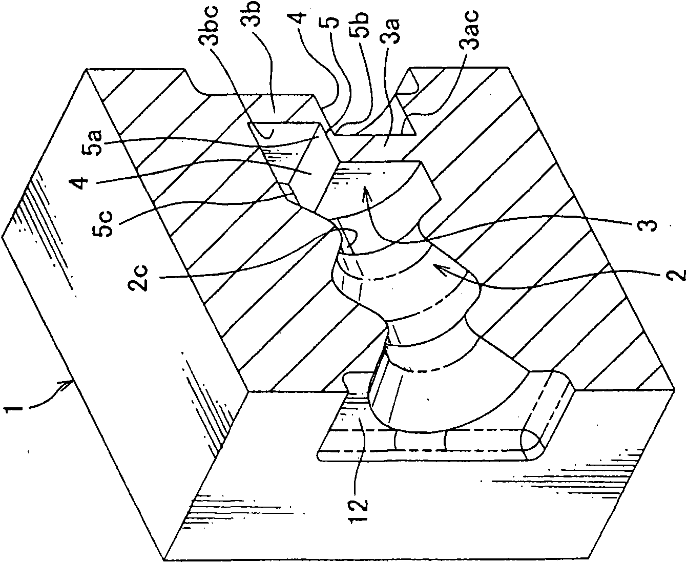
[0054] 1-4 show a first embodiment of the connector seal of the present invention.

[0055] see Figures 1A-2B , the connector seal 1 is made of (elastic) synthetic rubber, and has a plurality of terminal insertion holes 2 .

[0056] Each terminal insertion hole 2 has a diaphragm 3 including an upper diaphragm portion 3 a and a lower diaphragm portion 3 b. The upper and lower diaphragm portions 3 a , 3 b are spaced apart in the longitudinal direction of the terminal insertion hole 2 , and are connected to each other at the stepped portion 4 by the thin layer 5 .

[0057] see Figure 3A and 3B , when the terminal 6 is incorrectly inserted and taken out of the terminal insertion hole 2 , the vertical thin layer 5 of the diaphragm 3 breaks, and an opening 7 is formed in the radial or horizontal direction of the terminal insertion hole 2 . The chamber 2a below the upper membrane 3a and the chamber 2b above the lower membrane 3b then communicate with each other through the open...


PUM


Abstract

The invention provides a connector sealing element and allows the inspection of the existence of the opening which is not correctly formed in terminal insertion holes of the connector sealing part. The connector sealing element comprises a sealing part body and a plurality of terminal insertion holes each of which is provided with an upper diaphragm part and a lower diaphragm part which are mutually separated and which are connected through a thin layer. Preferably, the terminal insertion holes are provided with diaphragms and comprise an approximately bent groove and an approximately bent thin layer. Preferably, the terminal insertion holes are provided with diaphragms with thin layers which are located in the direction which is coincident with a diagonal of a rectangular cross section of the terminals so as to cause the angles of the terminals to collide against the correspondent ends of the thin layers.

Description

technical field [0001] The present invention relates to a connector seal having a septum disconnected by insertion of a terminal. Background technique [0002] Figure 16A and 16B A conventional connector seal is shown (FR 2844645-A1, Figure 2). [0003] This conventional connector seal 61 is made of rubber and has a mat shape to be attached to a connector housing (not shown). The connector seal 61 has a plurality of terminal insertion holes 62 on a seal main body (not shown). Each terminal insertion hole 62 integrally has a diaphragm 63 . The diaphragms 63 have stepped portions 64 and thin layers 65 interconnecting the stepped portions 64 on their respective surfaces. When the terminal 66 is inserted into the terminal insertion hole 62 , the diaphragm 63 is broken, and when further inserted, the outer surface of the wire connecting the terminal 66 is sealed by the lip 67 provided inside the insertion hole 62 . [0004] The connector includes a connector housing, termin...

Claims


Application Information

Patent Timeline
Patent Type & Authority Applications(China)
IPC IPC(8): H01R13/52
CPCH01R13/521
Inventor 笹木康弘田中茂杉山修黒泽亨山岸广明村越元贵
Owner YAZAKI CORP
Why Eureka
Try Eureka