
Coupling method of microstrip filter and microstrip resonator thereof

A microstrip filter and resonator technology, applied in the direction of resonators, waveguide devices, electrical components, etc., can solve the problems of small cross-coupling adjustable range, insufficient application of medium or superconducting film space, etc., to achieve The effect of large out-of-band suppression, small parasitic coupling, and high edge steepness

Active Publication Date: 2012-07-25
INST OF PHYSICS - CHINESE ACAD OF SCI
View PDF5 Cites 0 Cited by
  • Summary
  • Abstract
  • Description
  • Claims
  • Application Information

AI Technical Summary

Problems solved by technology

[0006] figure 2 Shown is a typical traditional filter topology (refer to H.Jia-Sheng, E.P.McErlean, and B.Karyamapudi, "High-order superconducting filter with group delay equalization, "2005, p.4pp.), its topology is One-dimensional, cross-coupling is introduced by adding coupling lines between non-adjacent resonators. There are two disadvantages of this coupling method: 1. The overall length of the filter is about the width of all resonators, dielectric or superconducting thin films The space cannot be fully used; 2. The two resonators that need to be cross-coupled are indirectly coupled through the coupling line, and the adjustable range of the cross-coupling during later tuning is relatively small

Method used


Image

  • Coupling method of microstrip filter and microstrip resonator thereof
  • Coupling method of microstrip filter and microstrip resonator thereof
  • Coupling method of microstrip filter and microstrip resonator thereof

Examples


Embodiment Construction

[0033] The present invention will be further described below in conjunction with the accompanying drawings and specific embodiments.

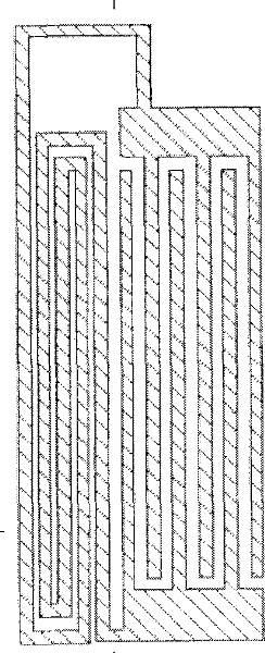
[0034] The planar superconducting microstrip resonator used in the present invention: includes a group of interfinger capacitors composed of microstrips, a group of double helix curve inductances and a group of bulk capacitors formed with the ground, and the microstrips include upper and lower two A layer of superconducting thin film and an artificial single crystal medium between the two layers of superconducting thin film, the insertion finger capacitance is connected in parallel with the double helix curve inductance, and the parallel connection of the insertion finger capacitance and the double helix curve inductance is connected with the Block capacitors are connected in series.

[0035] The block capacitors can be straight lines, broken lines, circles, rectangles, trapezoids, triangles or other arbitrary polygons, and the two block capacito...


PUM


Abstract

The invention relates to a coupling method of a microstrip filter and a microstrip resonator thereof. The resonator comprises a group of finger-inserting capacitors comprising microstrips, a group of double-helix curved inductors and a group of blocky capacitors formed with ground, wherein the microstrip comprises an upper-layer superconducting film, a lower-layer superconducting film and an artificial monocrystal medium positioned between the upper-layer and the lower-layer superconducting films; the finger-inserting capacitors are connected in parallel with the double-helix curved inductors, and the finger-inserting capacitors and the double-helix curved inductors connected in parallel are serially connected with the blocky capacitors; a line in the finger-inserting capacitors of the first resonator, which has the same charge polarity with an outermost line of the finger-inserting capacitor of the second resonator is shortened or cut off completely; and the outermost line of the finger-inserting capacitors of the second resonator is elongated and bent, extends into a line shortened or cut off completely in the finger-inserting capacitors of the first resonator and is coupled with two adjacent lines in the finger-inserting capacitors of the first resonator. The filter has less insertion loss, large out-band rejection, high band-edge gradient and good group delay performance.

Description

technical field [0001] The invention belongs to the field of microwave engineering. Specifically, the invention relates to a microstrip bandpass filter, a resonator and a coupling method made of a high-temperature superconducting thin film. Background technique [0002] In microwave engineering, superconducting microstrip resonators can form different orders of planar superconducting filters (a passive device), which are used in various microwave devices (such as radars, mobile phone base stations, microwave communication devices, radio astronomy telescopes) etc.), used to select a signal of a certain frequency. In the front end of various microwave receiving systems, filters are often used to suppress unwanted signal frequencies so that the required signal frequencies can pass through smoothly. High-temperature superconducting filter is a planar device made of high-temperature superconducting materials, which is composed of several planar resonators arranged according to c...

Claims


Application Information

Patent Timeline
Patent Type & Authority Patents(China)
IPC IPC(8): H01P5/04H01P1/203H01P7/08
Inventor 于涛李春光张强孙亮李翡王跃辉高路郭进边勇波黎红张雪强罗强顾长志何豫生
Owner INST OF PHYSICS - CHINESE ACAD OF SCI
Learn More