Composite transfusion pipe lined with fluorine resin or organic resin and producing method thereof
A technology of organic resin and manufacturing method, used in pipeline protection, mechanical equipment, pipeline protection through thermal insulation, etc., can solve problems such as products and process methods that are not involved, improve anti-waxing performance and corrosion resistance, and improve connection. Strength, the effect of improving thermal insulation performance
- Summary
- Abstract
- Description
- Claims
- Application Information
AI Technical Summary
Problems solved by technology
Method used
Image

Examples
Example Embodiment
[0043] Example 1:
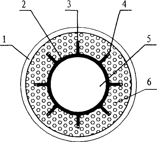
[0044] The cross-sectional structure diagram of the inner PP resin insulation oil pipeline figure 1 As shown, where: 1 is a steel oil pipeline, 2 is a PP organic resin tube, 3 is a PP organic resin tube boss, 4 is a PP organic resin tube boss gap, 5 is a PP organic resin tube inner cavity, and 6 is a phase change reservoir Polyurethane foam insulation material of energy material. The manufacturing process is as follows: Put the PP organic resin pipe into the inner cavity of the steel oil pipe 1, fix the PP organic resin pipe in the center of the steel oil pipe 1 with a positioning plate with holes, and pass the positioning plate hole into the pore between the steel oil pipe 1 and the PP organic resin pipe Pouring polyurethane foam insulation material 6 containing phase change energy storage materials, self-expanding polyurethane foam insulation material 6 containing phase change energy storage materials, connect the pores between the steel oil pipeline 1 and t...
Example Embodiment
[0046] Example 2:
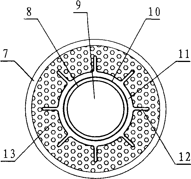
[0047] The cross-sectional structure diagram of the oil pipeline lined with aluminum alloy composite fluorine resin insulation figure 2 As shown, where: 7 is a steel oil pipe, 8 is a PTFE fluororesin pipe, 9 is a PTFE fluororesin pipe oil cavity, 10 is an F-4D fluoroplastic adhesive, 11 is an aluminum alloy tube, and 12 is an aluminum alloy tube wing fin, 13 is a polyurethane foam insulation material containing phase change energy storage materials. The manufacturing process is as follows: the inner layer of the aluminum alloy tube 11 is coated with F-4D fluoroplastic adhesive or the outer layer of the PTFE fluoroplastic tube 8 is coated with F-4D fluoroplastic adhesive 10, and the PTFE fluororesin tube 8 is placed in the aluminum alloy tube 11, the aluminum alloy tube 11 and PTFE fluororesin tube 8 are closed at both ends, and the inner cavity of the PTFE fluororesin tube is closed at both ends. 9 is filled with 1Mpa temperature 120℃ hot steam or 2Mpa tempera...
Example Embodiment
[0048] Example 3:
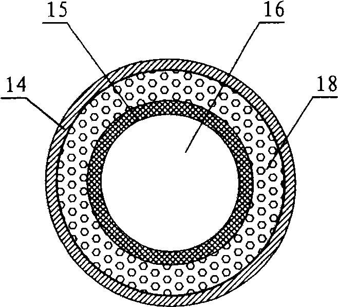
[0049] The cross-sectional structure diagram of the fluorine resin insulation oil pipeline lined with grooves is as shown image 3 As shown, Figure 4 Yes image 3 Longitudinal section structure diagram, in which: 14 is a steel oil pipeline, 15 is a PTFE fluororesin tube, 16 is a PTFE fluororesin tube inner cavity, 17 is a PTFE fluororesin tube groove, 18 is an insulation material containing phase change energy storage materials, 19 is Rock wool fire ring. The manufacturing process is as follows: the outer surface of the PTFE fluororesin tube 15 is coated with glue, the PTFE fluororesin tube 15 with groove 17 is inserted into the inner cavity of the steel oil pipe 14, one end is blocked with a rock wool fireproof ring 19, and a hole positioning plate is used Fix the PTFE fluororesin 15 tube in the center of the steel oil pipeline 14, and pour the insulation material 18 containing phase change energy storage material into the pore between the steel oil pipeline ...
PUM
 Abstract
Description
Claims
Application Information
 - R&D Engineer
- R&D Manager
- IP Professional
- Industry Leading Data Capabilities
- Powerful AI technology
- Patent DNA Extraction
Browse by: Latest US Patents, China's latest patents, Technical Efficacy Thesaurus, Application Domain, Technology Topic.
© 2024 PatSnap. All rights reserved.Legal|Privacy policy|Modern Slavery Act Transparency Statement|Sitemap