
Steam cleaner

A cleaner and steam technology, which is applied in the field of steam cleaners and can solve the problems of large volume of steam cleaners

Inactive Publication Date: 2010-07-28
SUZHOU HAAN TECH +1
View PDF2 Cites 0 Cited by
  • Summary
  • Abstract
  • Description
  • Claims
  • Application Information

AI Technical Summary

Problems solved by technology

Since the cylindrical tube is installed at the upper end of the rear housing, and the cylindrical tube is thicker than the thickness of the front housing, the entire steam cleaner feels bulky overall

Method used


Image

  • Steam cleaner
  • Steam cleaner
  • Steam cleaner

Examples


Embodiment Construction

[0061] The present invention will be further described below in combination with specific embodiments and accompanying drawings.

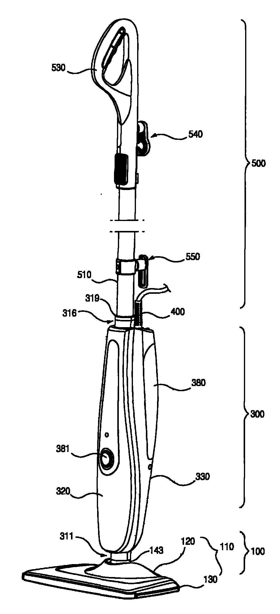
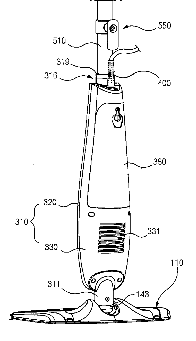
[0062] Such as figure 1 , figure 2 As shown, the steam cleaner in this embodiment is basically composed of a bottom part 100 and a main part 300 which is rotatably connected with the bottom assembly device 100 .

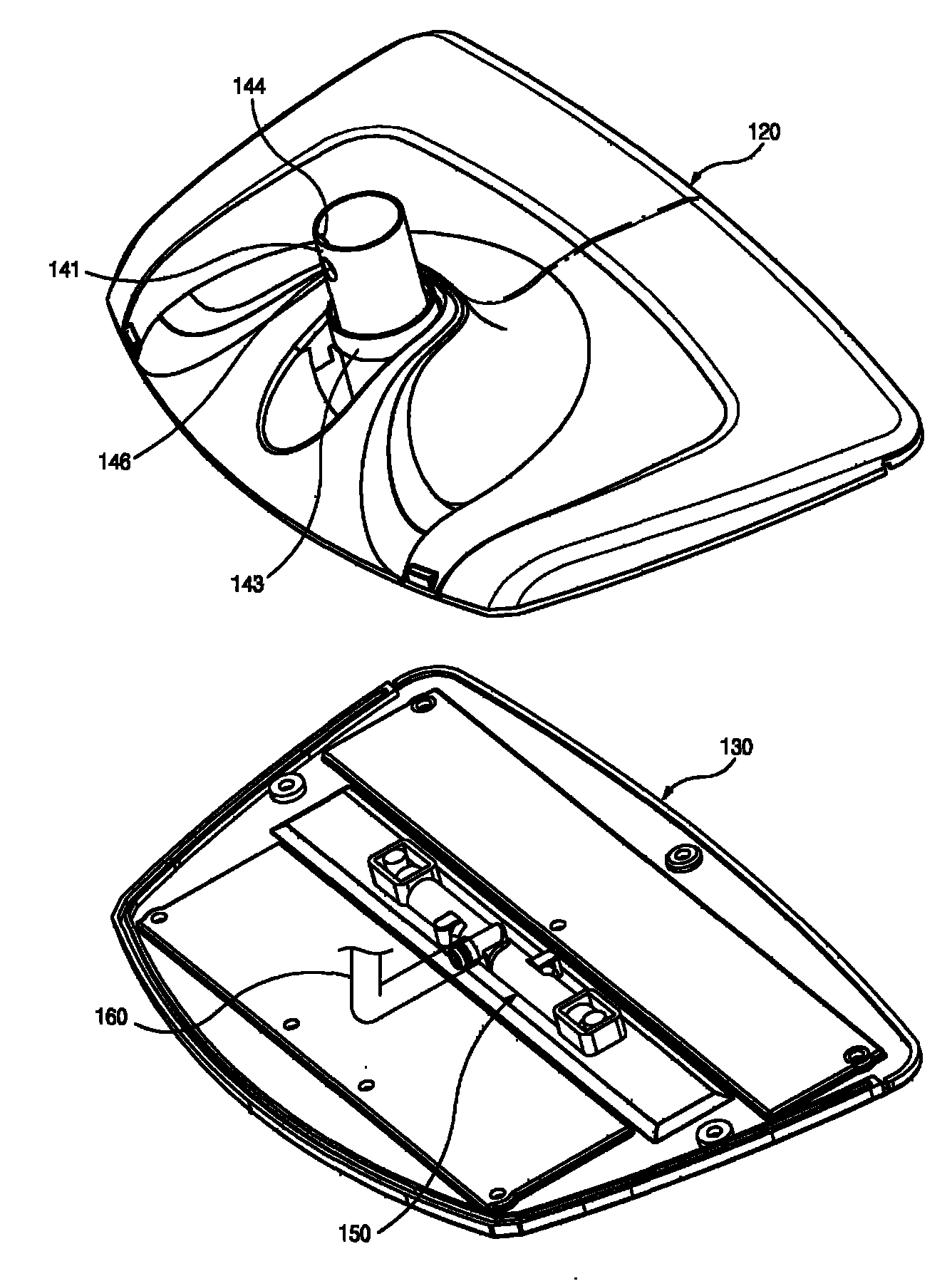
[0063] In general, if figure 1 , figure 2 , Figure 7 ~ Figure 9 As shown in , the main part 300 is generally composed of an outer shell 310 and a steam generator part 340 installed in the outer shell 310 . Such as figure 1 , image 3 , Figure 4 As shown, the bottom part 100 includes its main body 110. The main body 110 is mainly composed of an upper cover 120 and a bottom plate 130, wherein the bottom plate 130 is provided with a steam injection hole 131, and is installed on the inner side of the bottom plate 130 to communicate with the steam injection hole 131 and a steam supply pipe. 160 steam splitter 150.

[0064] The ...


PUM


Abstract

The invention relates to a steam cleaner, comprising a housing loaded with a steam generator and a main body provided with a steam spray hole, wherein a spile is formed at the lower end of the housing, the spile is inserted and installed in the hinged pat of the main body so that the housing is supported on the main body in a rotating manner in which the hinged part comprises a hinged shaft, a connecting pipe fixedly installed on the hinged shaft, and a slot part surrounding the connecting pipe and fixedly installed on the connecting pipe or the hinged shaft; the spile is nested in from the free end of the connecting pipe and the lower end thereof is blocked with the slot part. The steam cleaner in the invention plays a role of supporting and reinforcing the spile as the connecting pipe is inserted inside the spile, thereby overcoming rotary force or cutting force at the connection boundary surface with the hinged part and reducing the abrasion at the connection boundary surface.

Description

technical field [0001] The invention relates to a steam cleaner, and mainly relates to a connection structure between a casing carrying a steam generating device and a main body provided with steam injection holes. Background technique [0002] The connecting structure of the existing steam cleaner is disclosed in the Korean Registered Utility Model No. 20-0392095 communiqué, such as Figure 23 The shown steam cleaner is generally composed of a water tank 10 having both push rod and water supply functions, a heating water tank 40 forming a main body, a cover (not shown), and a bottom plate 60 . The upper end of the water tank 10 forms a handle support portion (not shown), and the lower end forms an insertion cylinder 14 . The upper end of the handle support part is inserted into a handle part (not shown), so that the handle part and the water tank 10 together function as a push rod. Concentric hinge shafts (not shown) are integrally formed on both sides of the cylindrical b...

Claims


Application Information

Patent Timeline
Patent Type & Authority Patents(China)
IPC IPC(8): B08B3/00
CPCA47L11/34A47L11/4036A47L11/4075
Inventor 韩京姬
Owner SUZHOU HAAN TECH
Learn More