
Charged particle ray irradiation device

A technology of charged particle beams and irradiation devices, applied in X-ray/γ-ray/particle irradiation therapy, using electric/magnetic devices to deflect/concentrate/focus the beam, radiation therapy, etc., can solve unrealistic, complicated control, etc. problem, to achieve the effect of suppressing unevenness and lowering

Active Publication Date: 2009-09-30
SUMITOMO HEAVY IND LTD
View PDF1 Cites 8 Cited by
  • Summary
  • Abstract
  • Description
  • Claims
  • Application Information

AI Technical Summary

Problems solved by technology

However, in this case, in the scanning method, it is necessary to control the intensity of the charged particle beam at high speed, and the control becomes complicated, so it is not practical.

Method used


Image

  • Charged particle ray irradiation device
  • Charged particle ray irradiation device
  • Charged particle ray irradiation device

Examples


Embodiment Construction

[0027] Hereinafter, preferred embodiments of the present invention will be described in detail with reference to the drawings. In addition, in the following description, the same code|symbol is attached|subjected to the same or corresponding element, and the overlapping description is abbreviate|omitted.

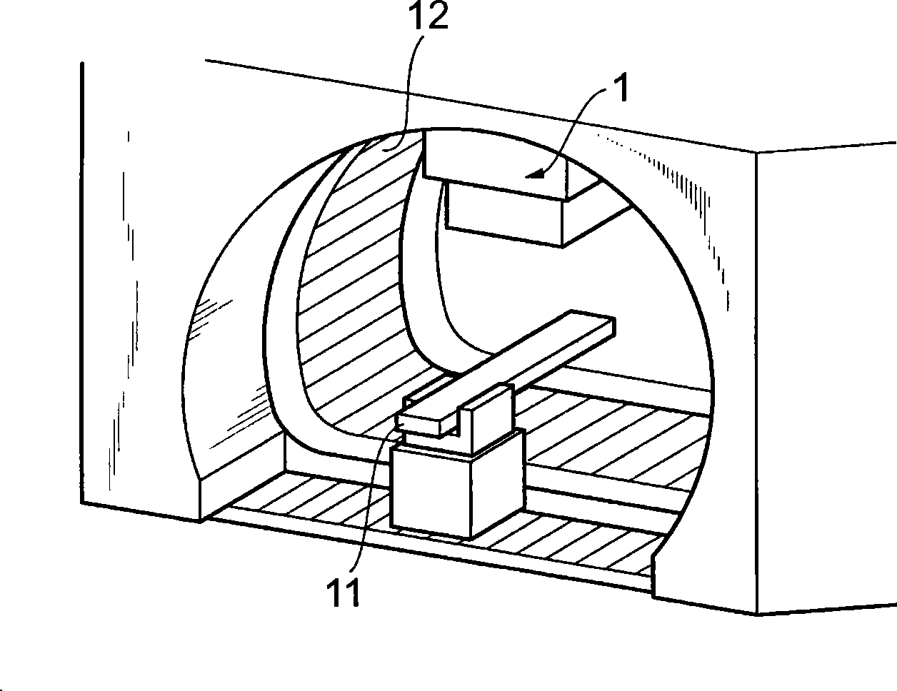
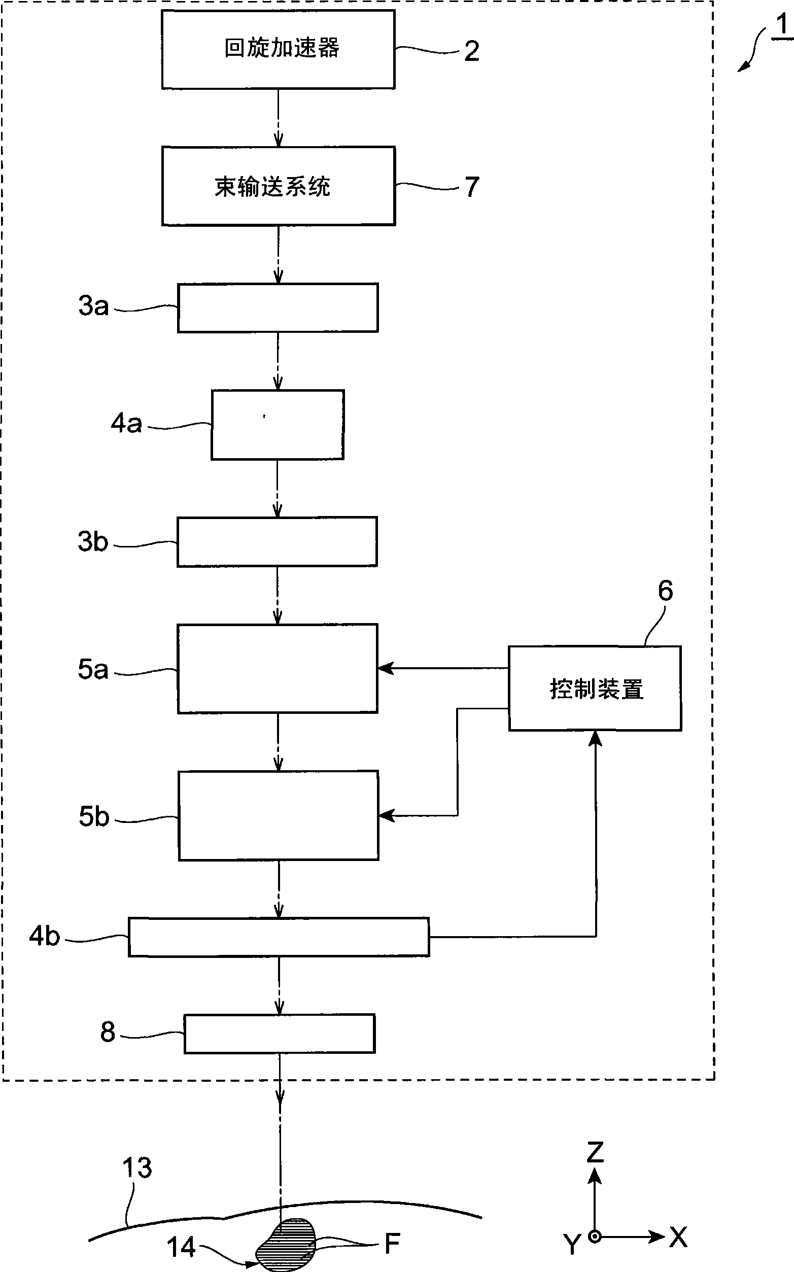
[0028] First, the charged particle beam irradiation apparatus according to the first embodiment of the present invention will be described. figure 1 It is a perspective view of the charged particle beam irradiation device according to the first embodiment of the present invention, figure 2 yes figure 1 Schematic diagram of the charged particle beam irradiation device. Such as figure 1 As shown, the charged particle beam irradiation apparatus 1 is an apparatus of the scanning method, is mounted on a rotating gantry 12 installed to surround the treatment table 11 , and can be rotated around the treatment table 11 by the rotation gantry 12 .

[0029] The charged particl...


PUM


Abstract

The invention provides a charged particle ray irradiation device capable of simply inhibiting unevenness and lowering of an edge portion of ray quantity distribution of the charged particle rays. The charged particle ray irradiation device (1) comprises scan electromagnets (5a, 5b) used for scanning a charged particle ray (R), and a control device (6) used for controlling the scan electromagnets (5a, 5b). In the charged particle ray irradiation device (1), a control mechanism (6) changes the scan speed when irradiating the charged particle ray (R) along the irradiation ray so as to modify theedge portion of ray quantity distribution of the charged particle ray (R). Thus, the edge portion of ray quantity distribution may be controlled without controlling intensity of the charged particle ray (R) such that unevenness and lowering of the edge portion of ray quantity distribution may be simply inhibited.

Description

technical field [0001] The present invention relates to a charged particle beam irradiation device based on a scanning method. Background technique [0002] Conventionally, as a charged particle beam irradiation device, for example, as described in Patent Document 1, a scanning method device is known. Such a charged particle beam irradiation device includes a scanning electromagnet for scanning the charged particle beam, and a control mechanism for controlling the operation of the scanning electromagnet, and scans the charged particle beam along the irradiation line in the irradiation area set on the object to be irradiated. Continuous irradiation on one side. [0003] [Patent Document 1] Japanese Patent Laid-Open No. 2002-22900 [0004] However, in the charged particle beam irradiation apparatus as described above, there is a possibility that the distribution of the dose of charged particle beams to be irradiated (hereinafter simply referred to as "beam dose distribution"...

Claims


Application Information

Patent Timeline
Patent Type & Authority Applications(China)
IPC IPC(8): A61N5/10A61B6/00G21K1/08
CPCA61N5/1043A61N5/10A61N5/1048A61N2005/1087A61N5/01
Inventor 立川敏树浅羽彻越智俊昭
Owner SUMITOMO HEAVY IND LTD
Learn More