
Gear and rack type isolated switch

A technology of isolating switch and rack and pinion, which is applied in the field of circuit breakers with meshing transmission devices, can solve the problems of easy tooth detachment, high cost of gear transmission structure, inconvenient assembly and maintenance, etc., and achieves small external dimensions and reduced volume. , the effect of easy assembly

Active Publication Date: 2009-09-23
青岛特锐德高压设备有限公司
View PDF1 Cites 11 Cited by
  • Summary
  • Abstract
  • Description
  • Claims
  • Application Information

AI Technical Summary

Problems solved by technology

Although this structure reduces the floor space of the isolating switch and improves the stability and service life, its gear transmission structure is expensive, easy to remove teeth, and inconvenient to assemble and maintain

Method used


Image

  • Gear and rack type isolated switch
  • Gear and rack type isolated switch
  • Gear and rack type isolated switch

Examples


Embodiment 1

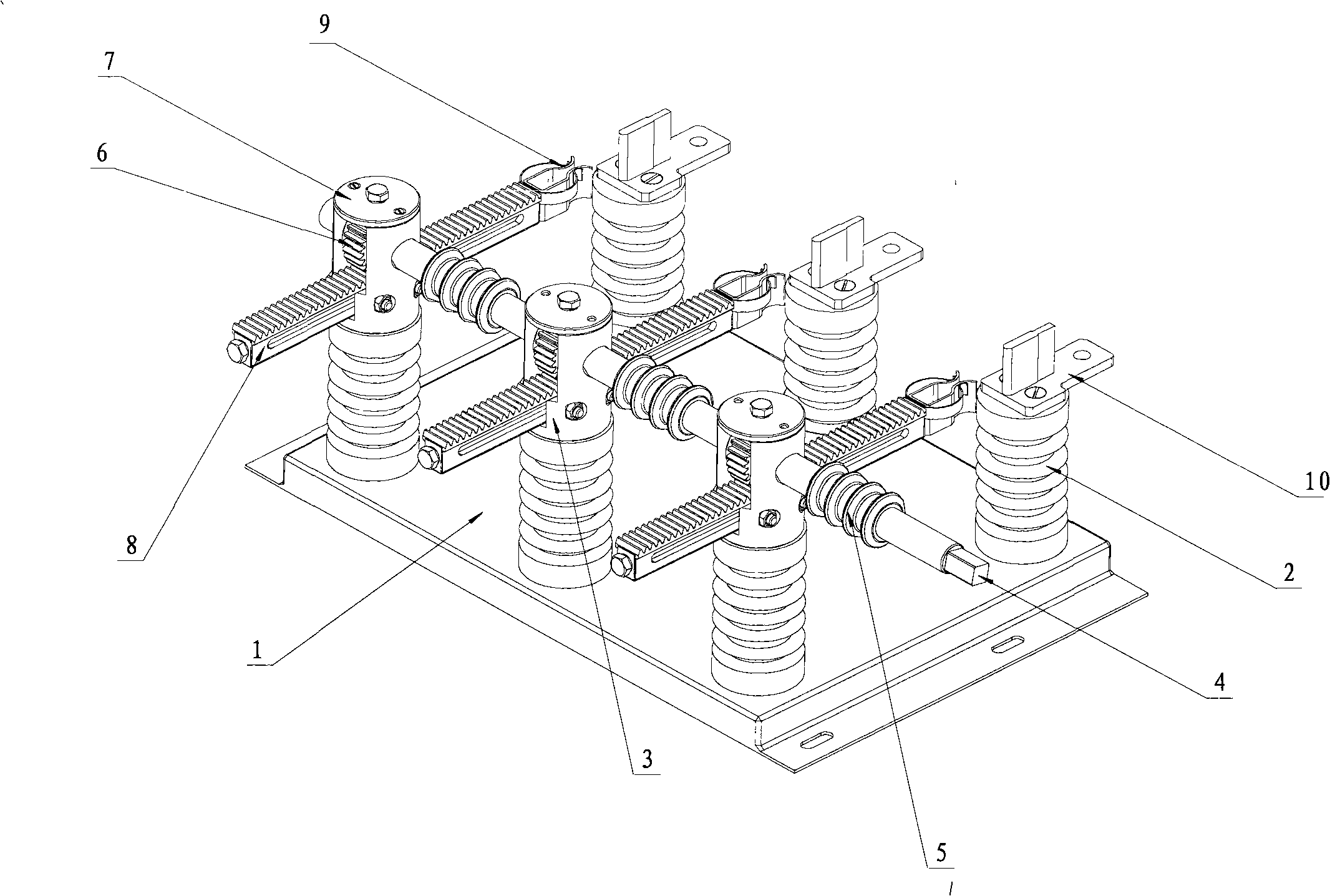
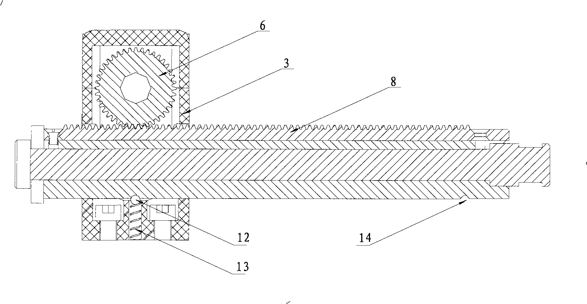
[0015] The device includes an isolation bracket 1, on which two insulating pillars 2 are respectively arranged for each phase, and there are two phase lines in total. Install the static contact 10 on one of the insulating pillars on each phase, and set the transmission box 3 on the other insulating pillar on each phase. The transmission box 3 is provided with a linear rack 8, and the linear rack 8 is opposite to the transmission box 3. It can move horizontally; the moving contact 9 is provided on the side adjacent to the linear rack 8 and the static contact 10; the gear 6 meshing with it is provided above the linear rack 8, and the two gears 6 are set on the same drive on the shaft 4 and can rotate synchronously with the drive shaft 4.

[0016] A cover 7 is provided on the upper side of the transmission case 3 . On the driving shaft 4, a creepage distance extender 5 is arranged between adjacent transmission boxes, and the creepage distance extender 5 is directly sleeved on th...

Embodiment 2

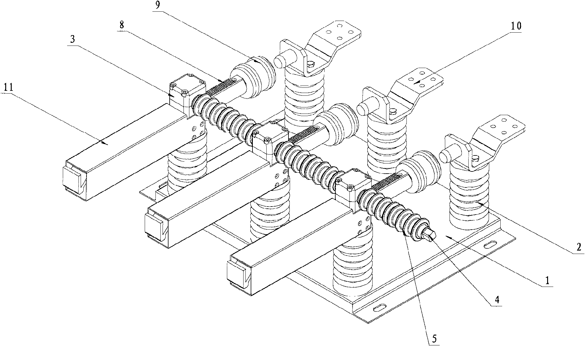
[0019] The device includes an isolation bracket 1, on which two insulating pillars 2 are respectively arranged for each phase, a total of three-phase lines. Install the static contact 10 on one of the insulating pillars on each phase, and set the transmission box 3 on the other insulating pillar on each phase. The transmission box 3 is provided with a linear rack 8, and the linear rack 8 is opposite to the transmission box 3 can move horizontally; the side near the linear rack 8 and the static contact 10 is provided with a movable contact 9, and the side far away from the linear rack 8 and the static contact 10 is provided with a protective cover 11 on the transmission box 3; the linear gear The top of the bar 8 is provided with a gear 6 meshed with it, and the three gears 6 are all arranged on the same drive shaft 4 and can rotate synchronously with the drive shaft 4, and the rotation of the gear 6 drives the linear rack 8 to move linearly.

[0020] A cover 7 is provided on t...


PUM


Abstract

The invention relates to a high-pressure air circuit breaker, in particular to a circuit breaker with a meshing driving device. A gear and rack type isolated switch of the invention comprises an isolated bracket; each phase of the isolated bracket is provided with two insulated struts; one of the insulated struts of each phase is provided with a static contact, while other insulated strut is provided with a driving box which is provided with a rack; the rack can horizontally move relative to the driving box; one side of the rack close to the static contact is provided with a moving contact; the horizontal movement of the rack realizes the separation and closing of the moving contact and the static contact; gears meshed with the rack are arranged above the strip rack; and all gears are arranged on the same driving shaft and can synchronously rotate with the driving shaft. The gear and rack type isolated switch has the advantages of reliable drive, high intensity, convenient assembly, great reduction of cabinet volume, and guarantee of intensification and miniaturization of power equipment, and the like.

Description

technical field [0001] The invention relates to a high-voltage air circuit breaker, in particular to a circuit breaker with an engaging transmission device. Background technique [0002] The isolating switch is a commonly used device in high-voltage substations. Its working principle is to connect the two ends with a swing arm set in the middle of each phase line that can rotate 90 degrees horizontally. The swing arm is a fixed straight rod. When closing Rotate the swing arm so that both ends are inserted into the two ends respectively; when opening the gate, rotate the swing arm 90 degrees. This kind of isolating switch has simple structure and low commissioning cost, and can meet the requirements of various environments. With the advancement of science and technology, power equipment is becoming more and more intelligent and intensive. Now the widely used isolating switches mostly use rocker arm opening and closing mechanisms in terms of structure. The so-called rocker ar...

Claims


Application Information

Patent Timeline
IPC IPC(8): H01H31/32H01H3/40
Inventor 孙福鹏于德翔屈东明刘洪玲王怀源刘思凝张子昭牛纯刚
Owner 青岛特锐德高压设备有限公司
Learn More