Die adjusting mechanism

A technology for adjusting mechanisms and molds, applied to presses, manufacturing tools, etc., can solve problems such as high prices, simple, and complex structures

Inactive Publication Date: 2009-09-23
竺祖德 +4
View PDF1 Cites 3 Cited by
  • Summary
  • Abstract
  • Description
  • Claims
  • Application Information

AI Technical Summary

Problems solved by technology

[0002] The current domestic general powder metallurgy press has a single function and can only produce parts with simple shapes, so there is no mold adjustment mechanism
The dedicated powder metallurgy press, whether imported or domestic, is too complicated in structure, bulky, and too expensive, which discourages most companies in this industry. Therefore, how to reduce the cost of parts while ensuring the quality of powder metallurgy parts Cost has become a big problem in the industry
[0003] In order to solve this problem, a more feasible solution has been proposed in the patent of the powder molding machine mold frame stopper adjustment mechanism (patent number: ZL01239490.4). The height of the punching block changes the position of the mold accordingly, and the up and down of a pair of blocks can be adjusted simultaneously or separately to adjust the position of the mold installed on the multi-layer formwork, that is, the same mold base can be used to press out more Parts with complex shapes, but due to the simple structure of the whole mechanism, the height adjustment range of the first and second lower punch stops is too small, and it is difficult to ensure the parallelism of the stops during the adjustment process, so only some parts with complex shapes can be pressed. The life of the mold is also restricted

Method used


Image

  • Die adjusting mechanism
  • Die adjusting mechanism
  • Die adjusting mechanism

Examples


Embodiment Construction

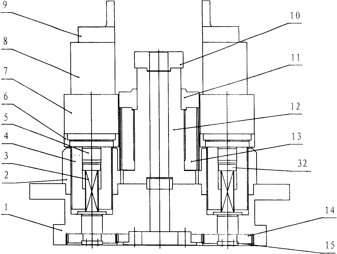
[0013] Among the figure, 1, there are two grooves and a plurality of shaft holes in the base (1), and the fixed screw sleeve (2) is inserted in the groove, with an interference fit between them, and the inner hole of the fixed screw sleeve (2) has threads.

[0014] 2. The head and tail of the adjustment shaft (3) have screw holes, and the upper part is rectangular. The adjustment shaft (3) is inserted into the shaft hole of the base (1), and one end of the center hole of the adjustment stud (4) is a circle. hole, the other end is a rectangular hole matching the adjustment shaft (3), and the outer circle is provided with threads. The rectangular hole of the adjustment stud (4) is inserted into the adjustment shaft (3) and then screwed into the fixed screw sleeve (2). Upper gear (14), shaft cover (15), limit block (32).

[0015] 3. The block adjustment stud (12) and the positioning sleeve (29) are placed on the base (1) and fixed with screws, the gear (13) is screwed on the bloc...


PUM


Abstract

The invention provides a die adjusting mechanism for a powder metallurgy forming machine. The die adjusting mechanism can make dies always be in a horizontal status during the adjustment, greatly improve the permissible adjusting range, realize the precision control through a counter in a control mechanism, and obviously improve the repeated precision of daily adjustment. The die adjusting mechanism comprises a first punch die adjusting mechanism and a second punch die adjusting mechanism. All the mechanisms are arranged on a base (1), wherein a control mechanism (18) drives a gear (13) to run through a gear drive mechanism; and a second undershoot stopper (11) goes up and down with the gear. A control mechanism (30) drives two gears (14) to run through a gear drive mechanism so as to make an adjusting stud (4) go up and down; and a first undershoot stopper (9) arranged on the upper part of the adjusting stud goes up and down with the adjusting stud. Therefore, the mechanism can simultaneously or separately adjust the up-and-down movement of a pair of stoppers so as to reach the aim of adjusting the position of the dies arranged on a multilayer template.

Description

technical field [0001] The invention relates to a mold height adjusting device of a powder metallurgy forming machine. Background technique [0002] The general powder metallurgy press made in China now has a single function and can only produce parts with simple shapes, so there is no mold adjustment mechanism. The dedicated powder metallurgy press, whether imported or domestic, is too complicated in structure, bulky, and too expensive, which discourages most companies in this industry. Therefore, how to reduce the cost of parts while ensuring the quality of powder metallurgy parts Cost has become a major problem in the industry. [0003] In order to solve this problem, a more feasible solution has been proposed in the patent of the powder molding machine mold frame stopper adjustment mechanism (patent number: ZL01239490.4). The height of the punching block changes the position of the mold accordingly, and the up and down of a pair of blocks can be adjusted simultaneously...

Claims


Application Information

Patent Timeline
IPC IPC(8): B22F3/03B30B15/00
Inventor 蒋文龙钟迎霞
Owner 竺祖德
Why Eureka
Try Eureka