
Piston pump, in particular fuel pump, having roller tappet

A piston pump and high-pressure fuel pump technology, applied in fuel injection pumps, fuel injection devices, pumps, etc., can solve problems such as strong wear and tear, and achieve the effect of not easy to wear and long service life

Inactive Publication Date: 2009-09-09
ROBERT BOSCH GMBH
View PDF1 Cites 9 Cited by
  • Summary
  • Abstract
  • Description
  • Claims
  • Application Information

AI Technical Summary

Problems solved by technology

Uncontrolled axial movement of the rollers onto other components can lead to high wear of the associated components

Method used


Image

  • Piston pump, in particular fuel pump, having roller tappet
  • Piston pump, in particular fuel pump, having roller tappet
  • Piston pump, in particular fuel pump, having roller tappet

Examples


Embodiment Construction

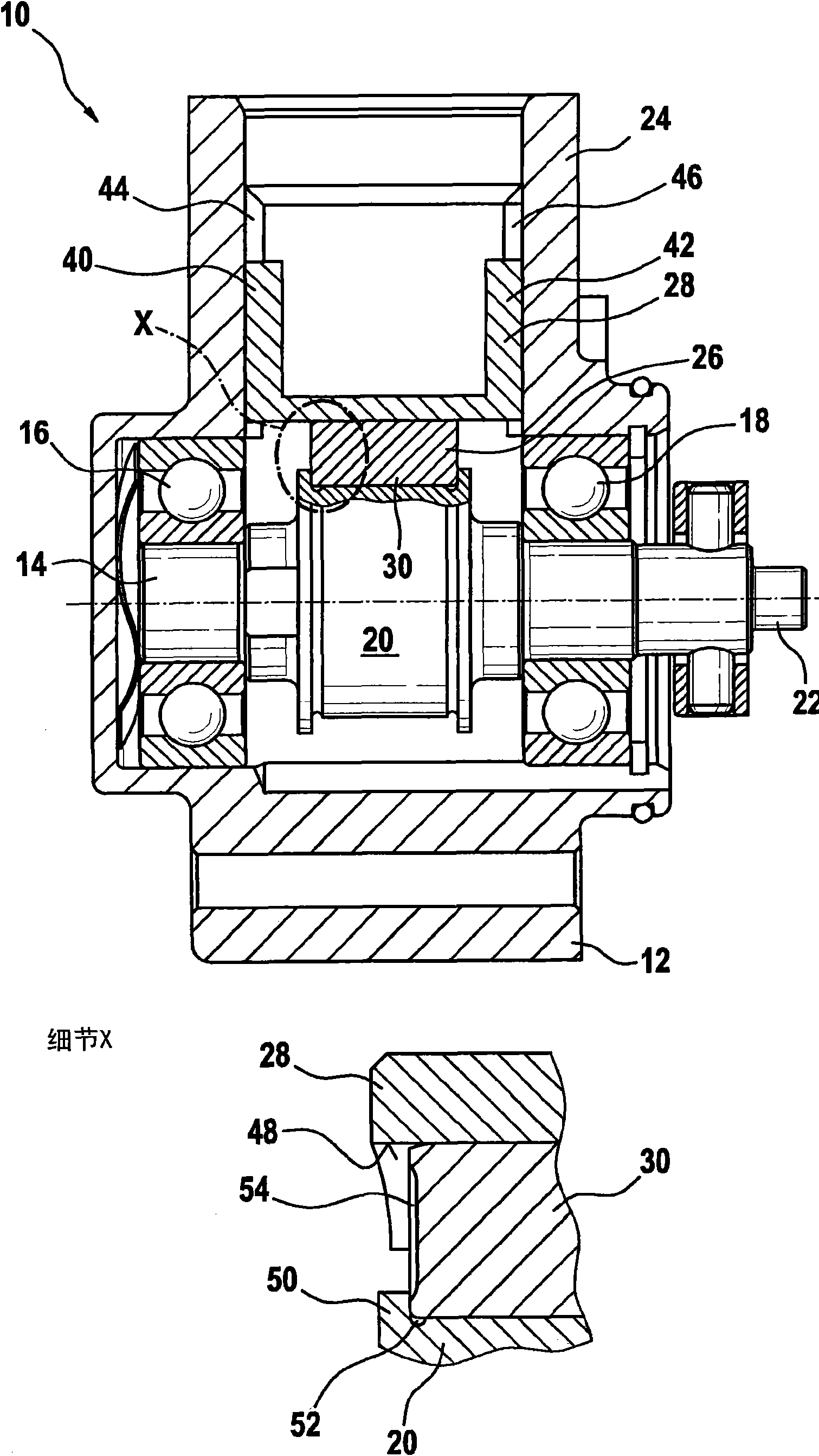
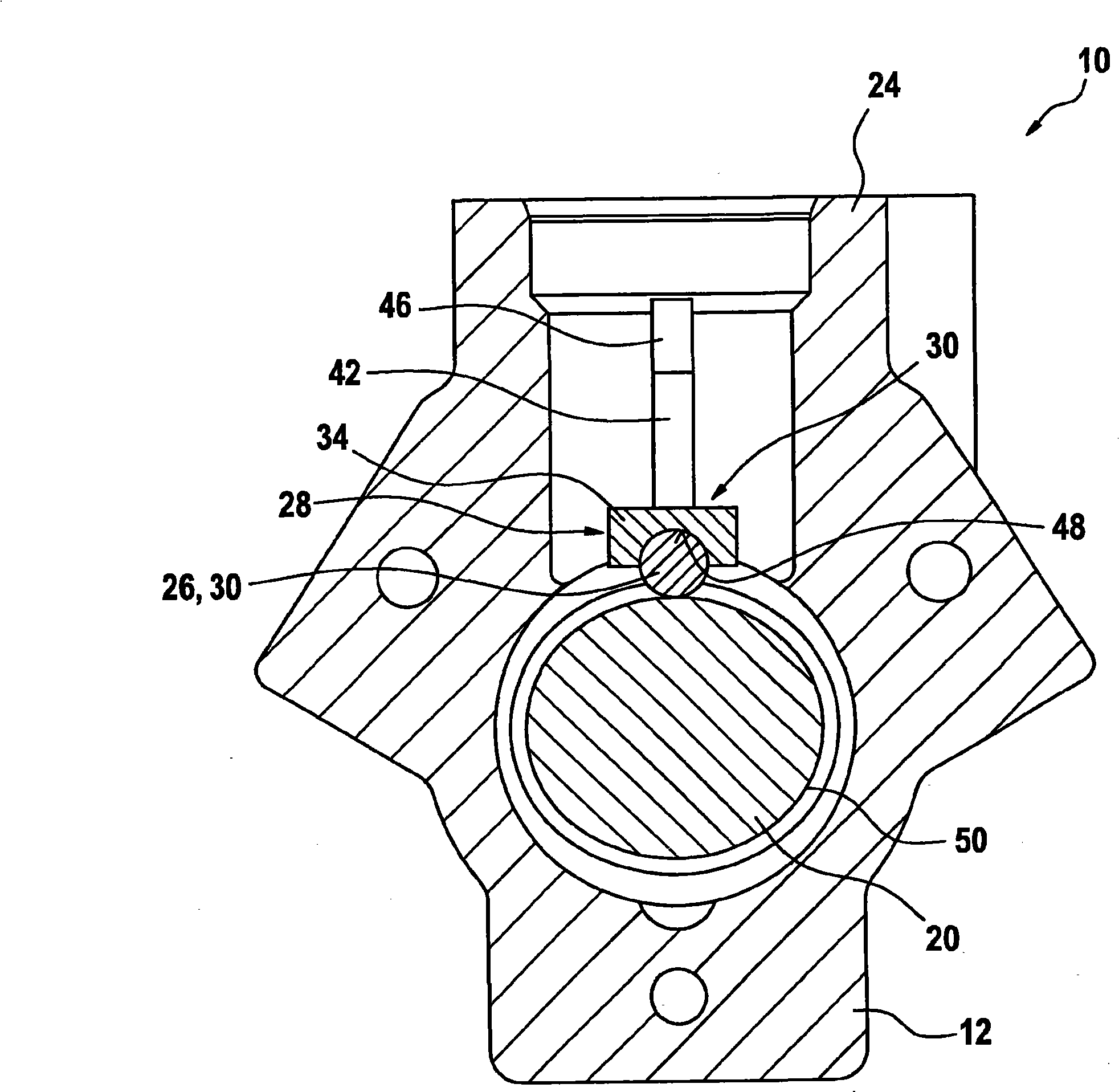
[0021] figure 1 The piston pump in is indicated generally by reference numeral 10 . It comprises a housing 12 in which a drive shaft 14 is supported via two bearings 16 and 18 . especially by figure 2 It can be seen that the drive shaft 14 comprises, between the two bearings 16 and 18 , a cam section 20 with an oblong cross-section.

[0022] figure 1 and 2 The piston pump 10 shown in is used as a high-pressure fuel pump for internal combustion engines in automobiles. With the high pressure fuel pump, fuel is compressed to very high pressure and delivered to a fuel rail (not shown). In this case, the drive shaft 14 of the piston pump 10 is directly driven by the internal combustion engine. The drive shaft 14 is therefore provided with a corresponding coupling section 22 arranged outside the housing 2 .

[0023] The piston pump 10 is a single-cylinder radial piston pump. For the sake of clarity, however, neither the piston nor the delivery chamber delimited by it and th...


PUM


Abstract

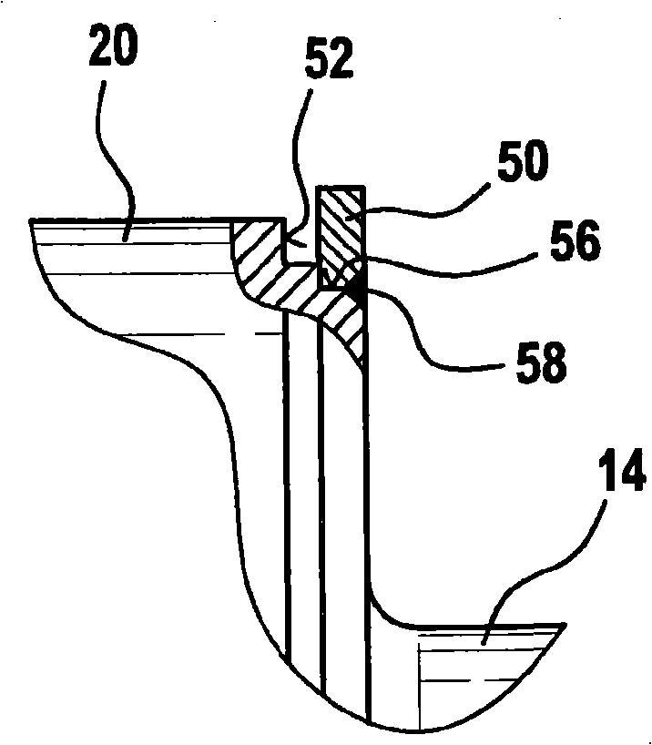
Proposed is a piston pump having a roller tappet (26), in which a collar (50) is provided at the side of a cam section (20) of a driveshaft, on which collar (50) a roller (30) can run during operation.

Description

technical field [0001] The invention relates to a piston pump, in particular a high-pressure fuel pump, having a housing, a piston, and a drive shaft with an eccentric or cam section, the piston being supported on the eccentric at least indirectly via a push rod element section or cam section. Background technique [0002] A piston pump of the type mentioned at the outset is known from DE 43 00 631 A1. The fuel injection pump described in this document is provided with a piston which can be driven to and fro by a camshaft. Here, the piston is spring-loaded against the camshaft. In order to reduce the friction between the piston and the camshaft, a pushrod body with a roller shoe is attached to the base of the piston. A roller is rotatably supported and held on the roller shoe. The rollers roll on the cam track of the cam. An assembly including a push rod body, a roller shoe and a roller is called a roller push rod. [0003] A hydrodynamic sliding bearing is formed betw...

Claims


Application Information

Patent Timeline
Patent Type & Authority Applications(China)
IPC IPC(8): F02M59/10F04B1/04
CPCF04B1/0439F02M59/102
Inventor G·迈尔J·阿莱克尔A·詹特
Owner ROBERT BOSCH GMBH
Learn More