
Turbine heat shield assembly

A technology of heat shield and turbine impeller, which is applied to engine components, gas turbine devices, mechanical equipment, etc., can solve problems such as leakage, high cost, oil leakage, etc., and achieve the effect of contributing to manufacturing, maintaining efficiency, and being cost-effective.

Active Publication Date: 2009-09-09
BORGWARNER INC
View PDF10 Cites 5 Cited by
  • Summary
  • Abstract
  • Description
  • Claims
  • Application Information

AI Technical Summary

Problems solved by technology

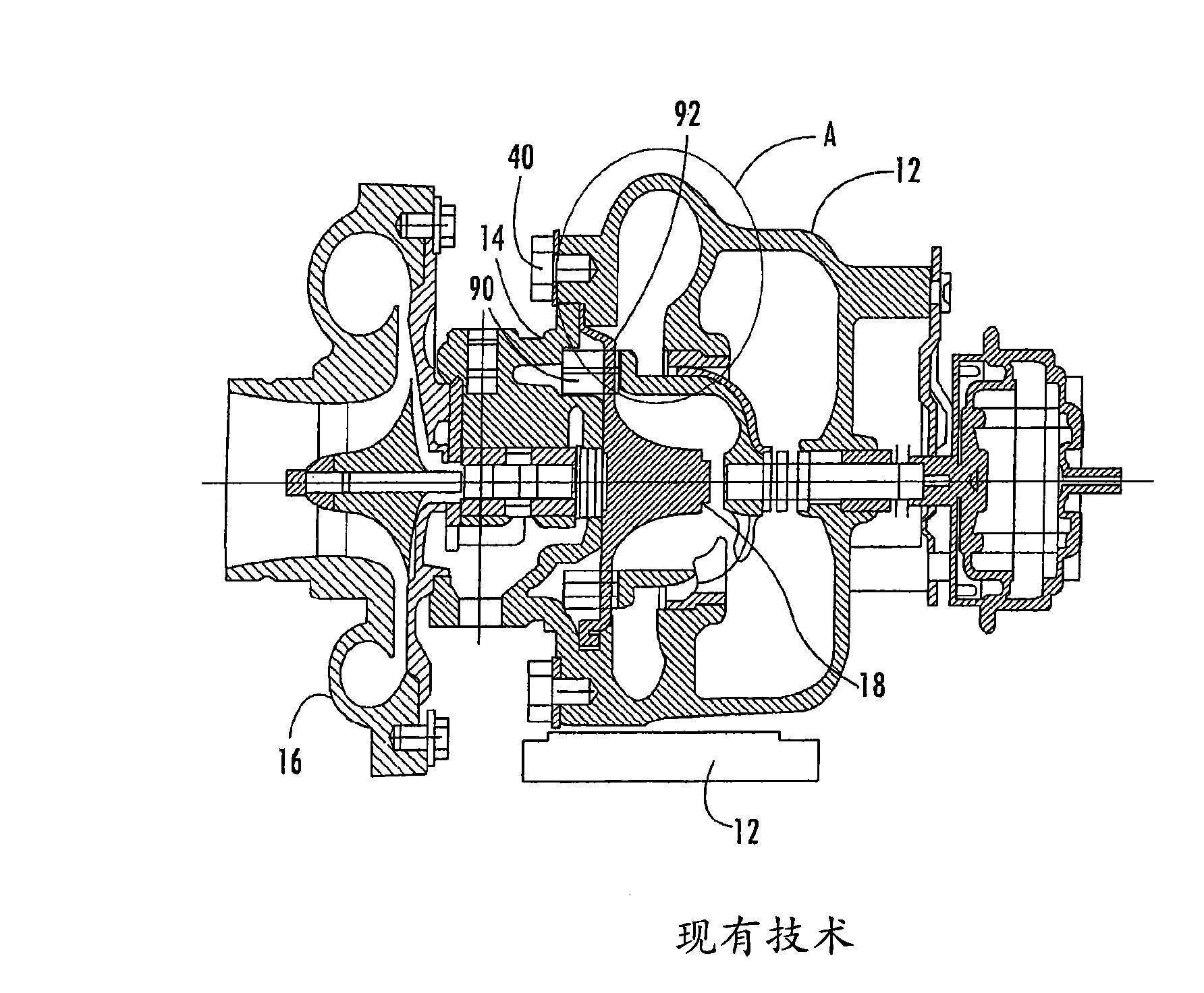
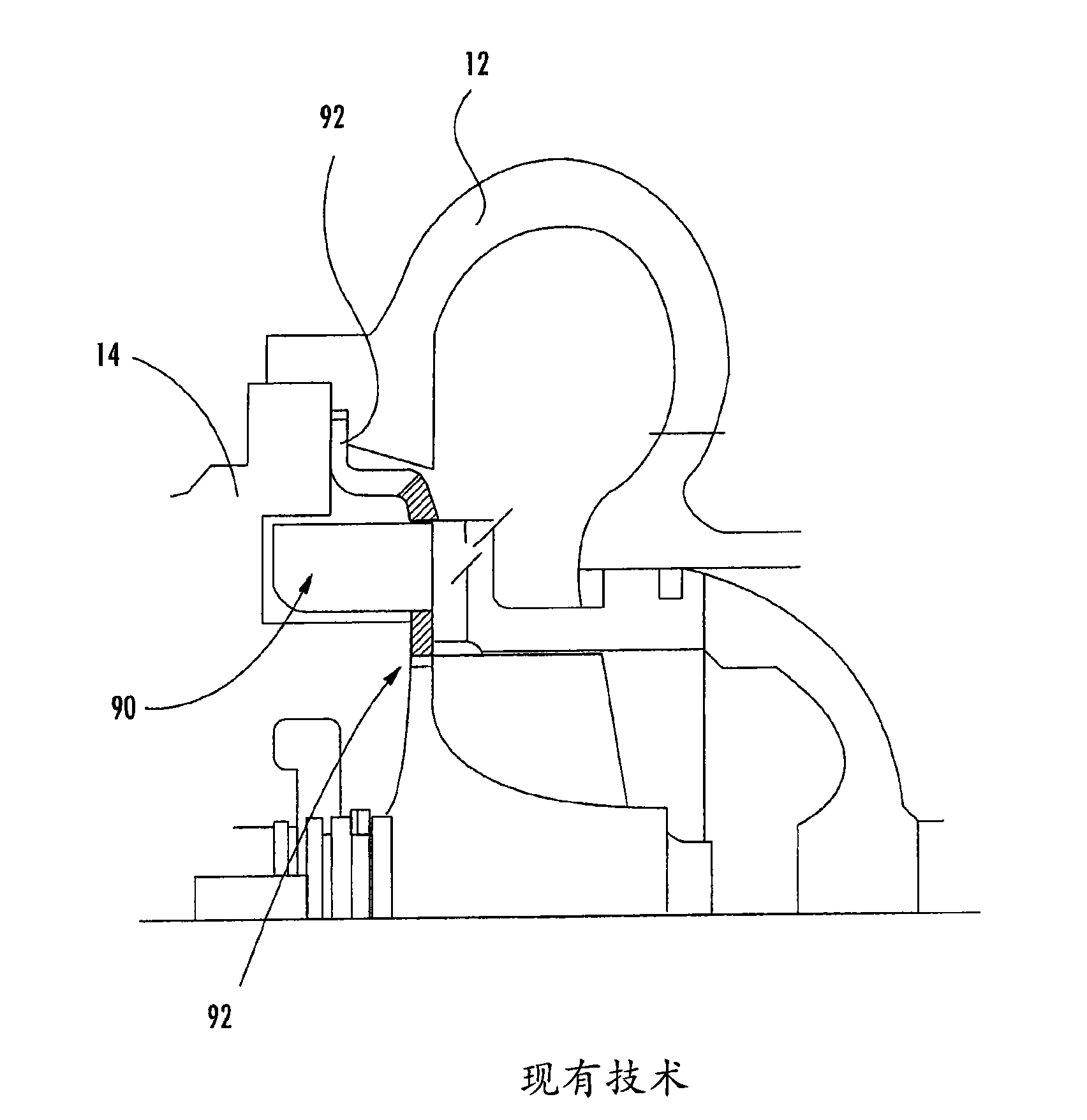
[0005] In addition to doing the useful job described above, a turbocharger must be designed to solve two obvious problems: First, oil should not be allowed to leak from the bearing housing into the turbine housing or compressor housing and from there to the environment Second, the high temperature of the turbine must not be allowed to adversely affect the lubricating oil in the bearing housing
Additional components such as connections such as bolts are costly and they can fail over time due to the extreme conditions these connections are subjected to

Method used


Image

  • Turbine heat shield assembly
  • Turbine heat shield assembly
  • Turbine heat shield assembly

Examples


Embodiment Construction

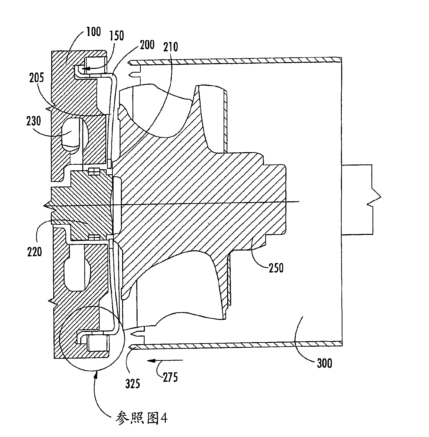
[0023] see image 3 and Figure 4 , a part of a turbocharger with a bearing housing 100 is shown in these figures. Bearing housing 100 defines a circumferential channel or recess 150 at one end near the periphery of the bearing housing. As will be explained in more detail below, channel 150 is used to position and connect a heat shield 200 to bearing housing 100 .

[0024] Preferably the channel 150 is concentrically aligned with a turbine wheel or rotor 250 . The heat shield 200 has a central hole 210 therethrough. Preferably the central bore 210 is concentrically aligned with the turbine wheel 250 and allows a shaft 220 to pass therethrough. Shaft 220 is attached at one end opposite a compressor wheel (not shown).

[0025] Heat shield 200 provides thermal protection for various components of the turbocharger, including lubrication system 230 . Various other components may be used with the turbocharger of the exemplary embodiment, but are not described. These other com...


PUM


Abstract

A turbocharger is provided having a bearing housing (100) and a heat shield (200) staked thereto. The staking process can be a compression staking process that deforms one or more portions of the bearing housing (100). The bearing housing (100) can have an annular channel (150) and the compression staking can be done to an outer edge (160) of the annular channel (150) to form one or more compression projections (400). The size and shape of the annular channel (150) can be substantially the same as the size and shape of an outer portion of the heat shield (200) to allow for a press-fit therebetween.

Description

technical field [0001] The present invention is directed to a turbocharger system for an internal combustion engine, and more particularly to the assembly of components of a turbocharger. Background technique [0002] A turbocharger is a type of forced induction system. They compress air to flow into an engine thereby increasing that engine's horsepower without adding significant weight. A turbocharger uses exhaust gas from the engine to spin a turbine that drives an air compressor. Because the turbine spins about 30 times faster than most car engines and the exhaust is plugged into the turbine, the temperature inside the turbine is very high. Furthermore, turbochargers are subject to noise and vibration due to the resulting high flow rates. These conditions can have adverse effects on some components of the turbocharger, especially rotating parts such as turbine rotors, which can lead to failure of the system. Furthermore, thermal growth or expansion due to temperature ...

Claims


Application Information

Patent Timeline
Patent Type & Authority Applications(China)
IPC IPC(8): F02B39/14F02B37/00F02B39/00
CPCF05D2230/60F02B39/14F05D2260/30F02C6/12F02B39/00F05D2260/231F05D2220/40Y10T29/4932F01D25/16F01D25/24
Inventor M·塞耶M·奥格尔
Owner BORGWARNER INC
Learn More