Battery jar voltage insulation test circuit based on linear optical coupler

A technology of voltage isolation and testing circuit, applied in the direction of voltage/current isolation, measuring current/voltage, measuring device, etc., can solve the problems of low cost, high cost, narrow circuit application range, etc., to prevent overvoltage output, simple matching , the effect of a wide input voltage range

Inactive Publication Date: 2009-09-02
CHINA NORTH IND GRP NO 70 RES INST
View PDF0 Cites 17 Cited by
  • Summary
  • Abstract
  • Description
  • Claims
  • Application Information

AI Technical Summary

Problems solved by technology

[0002] The battery voltage measurement is relatively simple in theory. The existing test methods are divided into two categories: isolated and non-isolated; for non-isolated measurement, the method of resistive voltage division is generally used. This method is low in cost and simple in circuit. However, the scope of application of the circuit is relatively narrow. In the case of 12V / 24V compatibility, it is difficult to match the voltage divider resistors.
The isolated measurement method is mainly completed in the form of an isolation amplifier. This method is costly, and the voltage range measured by the isolation amplifier is limited, so it is difficult to popularize in engineering applications.

Method used


Image

  • Battery jar voltage insulation test circuit based on linear optical coupler
  • Battery jar voltage insulation test circuit based on linear optical coupler

Examples


Embodiment Construction

[0011] The preferred embodiments of the present invention will be further described below in conjunction with the accompanying drawings.

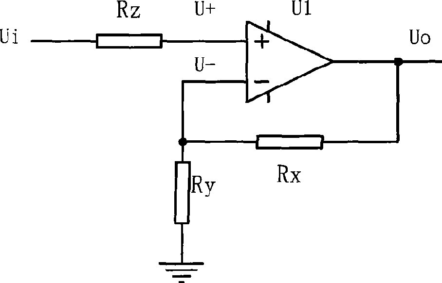
[0012] Such as figure 1 As shown, the basic working principle of the system can be simplified into a working model of a non-directional amplifier. According to the "virtual short" and "virtual break" principles of the amplifier, (U+)=(U-)=Ui, Uo=(1+ Rx / Ry)×Ui, where U+ is the positive input signal of the amplifier U1, U- is the negative input signal of the amplifier U1, Ui is the circuit input signal, Uo is the circuit output signal, and the resistor Ry is the negative input signal of the amplifier U1. Input the ground resistance, and the resistance Rx is the feedback resistance.

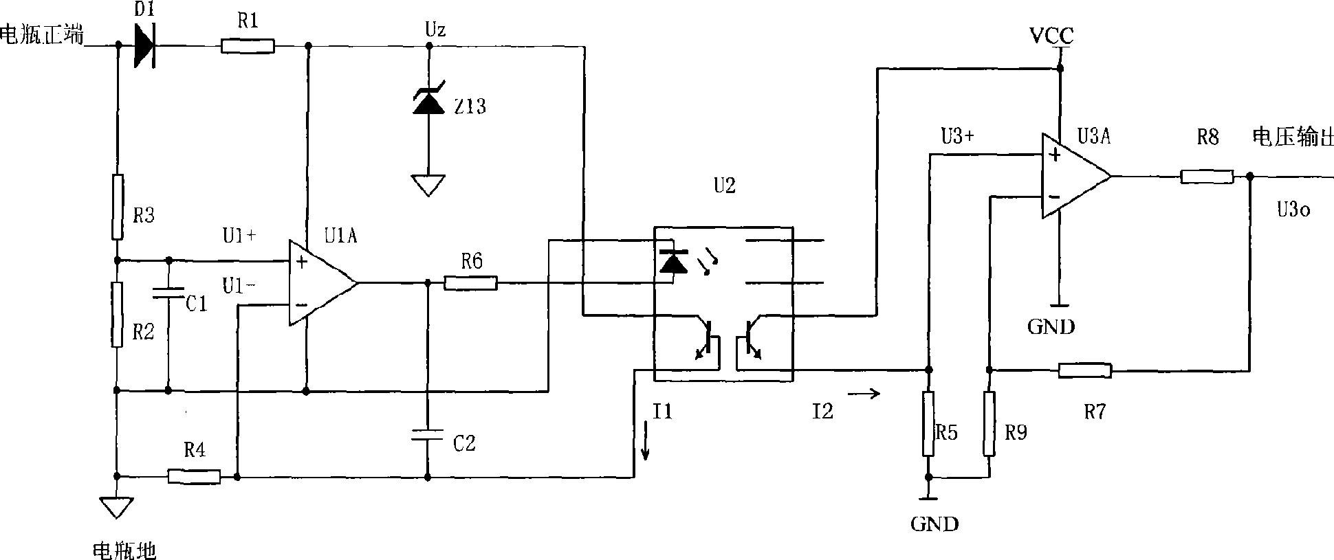
[0013] Such as figure 2 As shown, the battery voltage passes through the anti-reverse diode D1, and forms a stable voltage Uz through the current limiting resistor R1 and the voltage regulator tube Z13. On the one hand, it provides power to the amplifier U1A, ...


PUM


Abstract

The invention belongs to the technical field of engine electronic control, in particular relates to a battery jar voltage insulation test circuit based on a linear optical coupler. The circuit utilizes the double-output linear optical coupler, connects the input of the double-output linear optical coupler with one output to form a feedback amplifying element and accurately measures a battery jar power supply in an isolation condition by utilizing the characteristic that the current of two output ends of the double-output linear optical coupler is same; a battery jar voltage passes by a diode D1 capable of resisting reverse connection to form a stable voltage Uz by a current-limiting resistor R1 and a voltage regulator tube Z13, and the stable voltage Uz provides an amplifier U1A with a power supply and provides the output end of a linear photoelectric coupled device U2 with a current source. The invention has the advantage that a system has a wide suitable voltage range; the output stage of the circuit is powered by a subsequent modulus circuit power supply, and the circuit outputs in a similar drain open mode of a triode circuit so as to be simple to be matched with a system interface and effectively prevent the overpressure output of the circuit.

Description

technical field [0001] The invention belongs to the technical field of engine electronic control, and in particular relates to a battery voltage isolation test circuit based on a linear optocoupler. Background technique [0002] The battery voltage measurement is relatively simple in theory. The existing test methods are divided into two categories: isolated and non-isolated; for non-isolated measurement, the method of resistive voltage division is generally used. This method is low in cost and simple in circuit. However, the scope of application of the circuit is relatively narrow, and it is difficult to match the voltage divider resistors when 12V / 24V is required to be compatible. The isolated measurement method is mainly completed in the form of an isolation amplifier. This method is costly, and the voltage range measured by the isolation amplifier is limited, so it is difficult to popularize in engineering applications. Contents of the invention [0003] The purpose o...

Claims


Application Information

Patent Timeline
Patent Type & Authority Applications(China)
IPC IPC(8): G01R15/22G01R19/00
Inventor 孟长江王孝褚全红白思春胡勇焦玉琴张春杨俊恩
Owner CHINA NORTH IND GRP NO 70 RES INST
Why Eureka
Try Eureka