Floating roll device for splitting machine

A floating roller and slitting machine technology, which is used in transportation and packaging, metal processing, coiling strips, etc., can solve the problems of high requirements for floating roller material and processing, not meeting economic indicators and requirements, and difficult to improve, etc. Achieve the effect of simple structure, easy control and reduced resistance

Active Publication Date: 2011-03-23
南京安顺电气科技有限公司
View PDF0 Cites 3 Cited by
  • Summary
  • Abstract
  • Description
  • Claims
  • Application Information

AI Technical Summary

Problems solved by technology

The defect of this mechanism and method is that the way to establish the tension of the floating roller is to swing in the horizontal direction. The cylinder must first overcome the self-weight of the roller, but it is inconsistent with the direction of the tension. The precision of the whole mechanism makes the whole mechanism very large and complex. At the same time, the material and processing requirements of the floating roller are also very high, and the cost has increased a lot invisibly, which does not meet the economic indicators and requirements of industrial mass production.

Method used


Image

  • Floating roll device for splitting machine
  • Floating roll device for splitting machine
  • Floating roll device for splitting machine

Examples


Embodiment Construction

[0012] The present invention will be described in further detail below in conjunction with the accompanying drawings and specific embodiments.

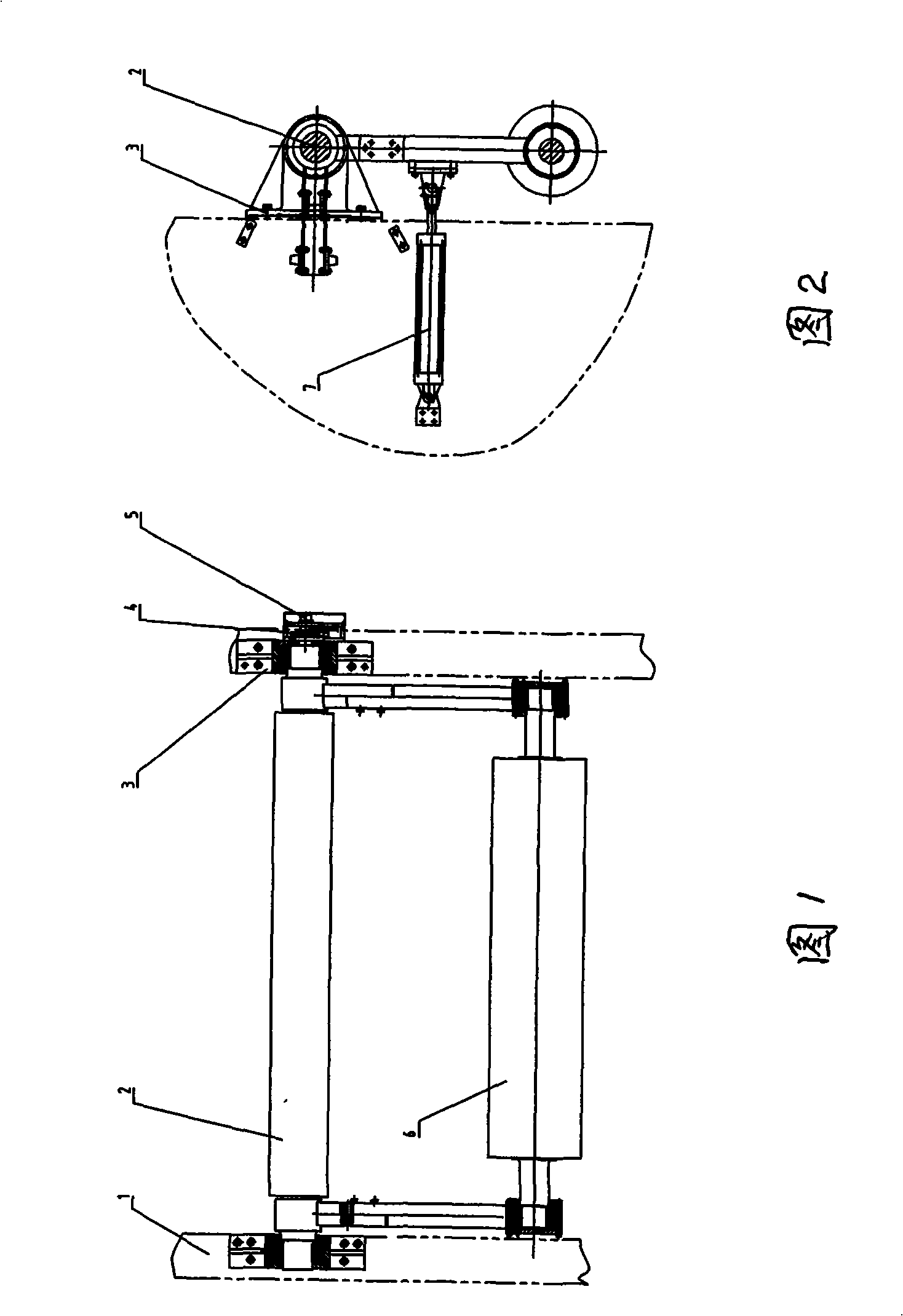
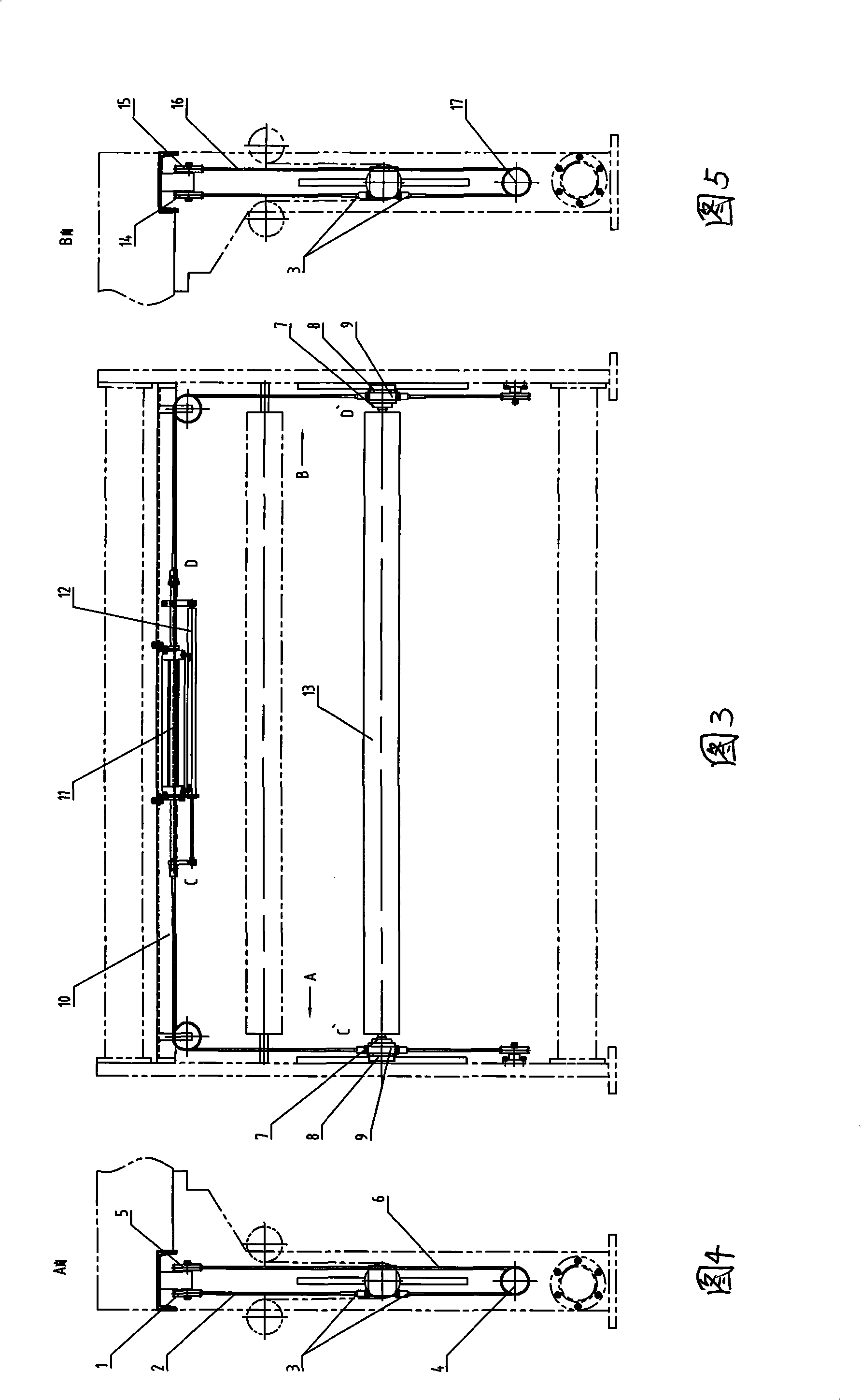
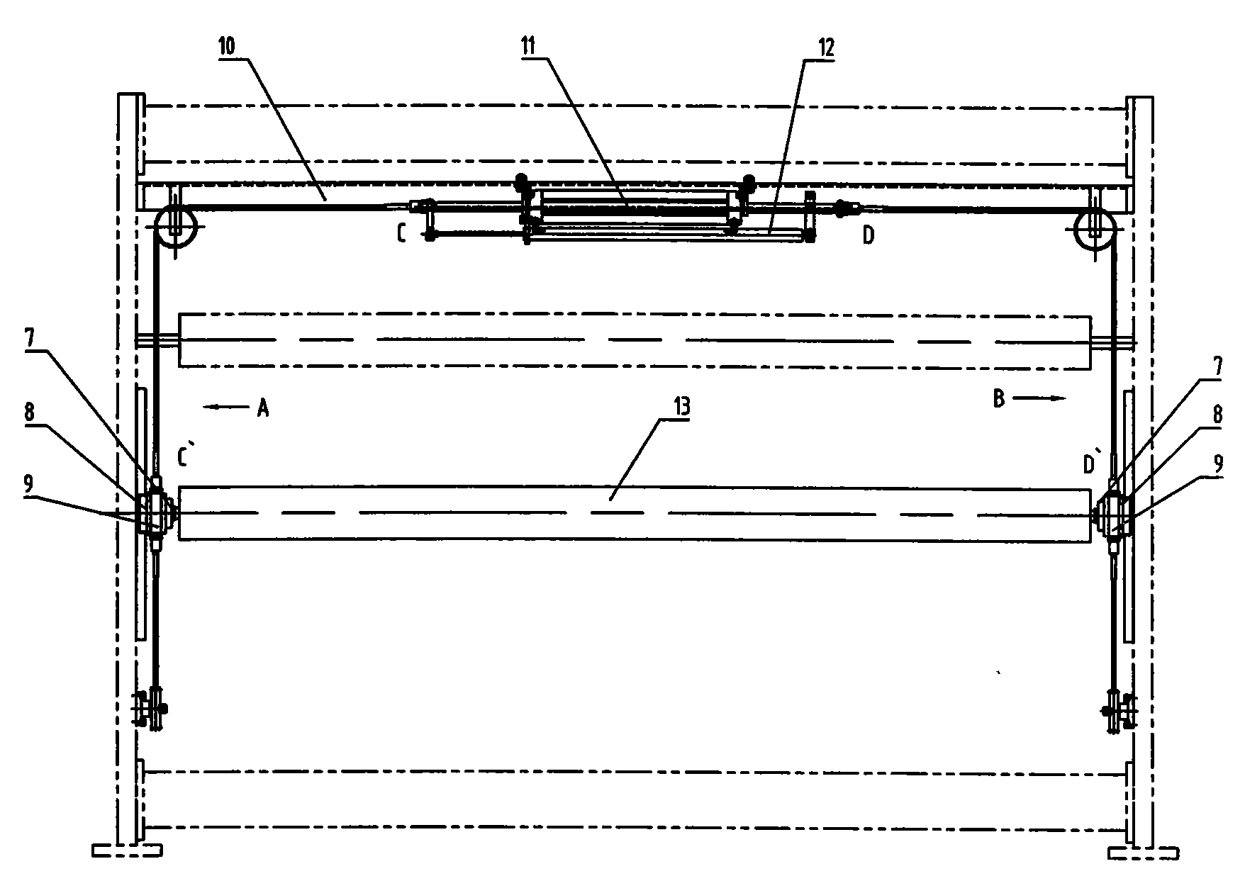
[0013] Such as image 3 , Figure 4 , Figure 5 Shown: the floating roller device for the slitting machine of this embodiment, on the position corresponding to the inside of the two wallboards, a linear guide rail is installed on one side, and the floating roller 13 passes through the circular outer spherical ball bearing 8 with a boss and the mounting plate 9 is installed on the linear guide rail slider, so that the floating roller 13 can move vertically up and down. The beam 10 installed with the double-rod double-acting standard cylinder 11 is also installed in the two wall panels and directly above the floating roller. Once the C end of the piston rod is stretched out, the position of the floating roller 13 is determined by detecting the movement of the piston rod of the cylinder. Stay rope I 2 goes around pulley I 1 and is co...


PUM


Abstract

The invention discloses a floating roll device for a splitting machine. Linear guide rails are vertically arranged at corresponding positions inside a wallboard, both ends of a floating roll are arranThe invention discloses a floating roll device for a splitting machine. Linear guide rails are vertically arranged at corresponding positions inside a wallboard, both ends of a floating roll are arranntee that both ends of the floating roll can move up and down simultaneously.antee that both ends of the floating roll can move up and down simultaneously.ged on a mounting plate first through a ball bearing with a lug boss and a circular outer ball surface and then integrally arranged on the linear guide rails to ensure that the floating roll can vertiged on a mounting plate first through a ball bearing with a lug boss and a circular outer ball surface and then integrally arranged on the linear guide rails to ensure that the floating roll can vertically move up and down, wherein the power for driving the floating roll to move only comes from a double-pole double-acting air cylinder, an extending end of the double-pole double-acting air cylindercally move up and down, wherein the power for driving the floating roll to move only comes from a double-pole double-acting air cylinder, an extending end of the double-pole double-acting air cylinder is connected with the upper part of one end of the floating roll through a pull rope, the other extending end of the double-pole double-acting air cylinder is connected with the lower part of the othis connected with the upper part of one end of the floating roll through a pull rope, the other extending end of the double-pole double-acting air cylinder is connected with the lower part of the other end of the floating roll through the pull, and the remained upper end of the floating roll is connected with the remained lower end by a pull rope. The action of the air cylinder structure can guarer end of the floating roll through the pull, and the remained upper end of the floating roll is connected with the remained lower end by a pull rope. The action of the air cylinder structure can guara

Description

technical field [0001] The invention relates to a floating roller on a slitting machine, in particular to a floating roller in a vertical movement mode on a slitting machine. Background technique [0002] Before the present invention, the main function of the floating roller on the station-type winding and slitting machine was to establish tension on the material to be cut and rolled, so that the rolled material was flat, smooth and uniform, thereby ensuring the quality of the rolled material, A little jitter and unevenness will make the winding materials become waste products and defective products, resulting in reduced quality, economic losses, increased costs, and damage to reputation. Therefore, in order to ensure the quality of the rewinding material, the key is to improve the floating roller of the rewinding material, which must be able to establish tension on the rewinding material, and improve the adjustment accuracy, so as to prevent the tension caused by the slight...

Claims


Application Information

Patent Timeline
Patent Type & Authority Patents(China)
IPC IPC(8): B65H23/26B26D7/27
Inventor 马寅
Owner 南京安顺电气科技有限公司
Why Eureka
Try Eureka