Ratchet swinging magnetic engine

A magnetic motor and magnet technology, applied in the direction of generators/motors, electromechanical devices, electric components, etc., can solve the problems of high switching energy consumption, pollute the environment, hinder the rotation of the flywheel, etc., and achieve the effect of low switching energy consumption

Inactive Publication Date: 2009-08-26
胥明山 +1
View PDF0 Cites 0 Cited by
  • Summary
  • Abstract
  • Description
  • Claims
  • Application Information

AI Technical Summary

Problems solved by technology

[0002] At present, the power machinery used at home and abroad basically needs to be supplied with traditional coal, electricity, and oil energy sources to perform work, which seriously pollutes the environment, coupled with energy shortages, so it is a never-ending subject to explore and replace traditional energy engines.
For a long time, there have been many researches and inventions on magnetic motors using permanent magnetic energy, but almost none of them can be practically applied. The reasons are: ①There is no substance that can cut off the magnetic field lines of two magnets with opposite sexes and then control the on-off of their suction to perform work; ②If you use a shield The switch is cut off, the switch consumes too much energy, and the magnetic energy cannot do work; ③The switching speed is difficult to accurately control. The strong suction generated by cutting off the magnetic force line at the top dead center of the flywheel will seriously hinder the rotation of the flywheel

Method used


Image

  • Ratchet swinging magnetic engine
  • Ratchet swinging magnetic engine

Examples


specific Embodiment approach

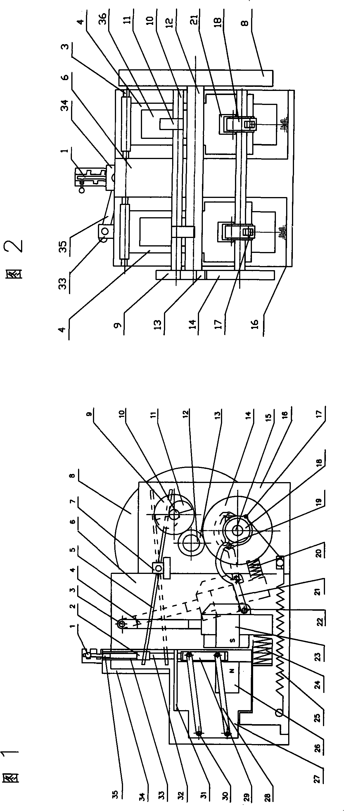
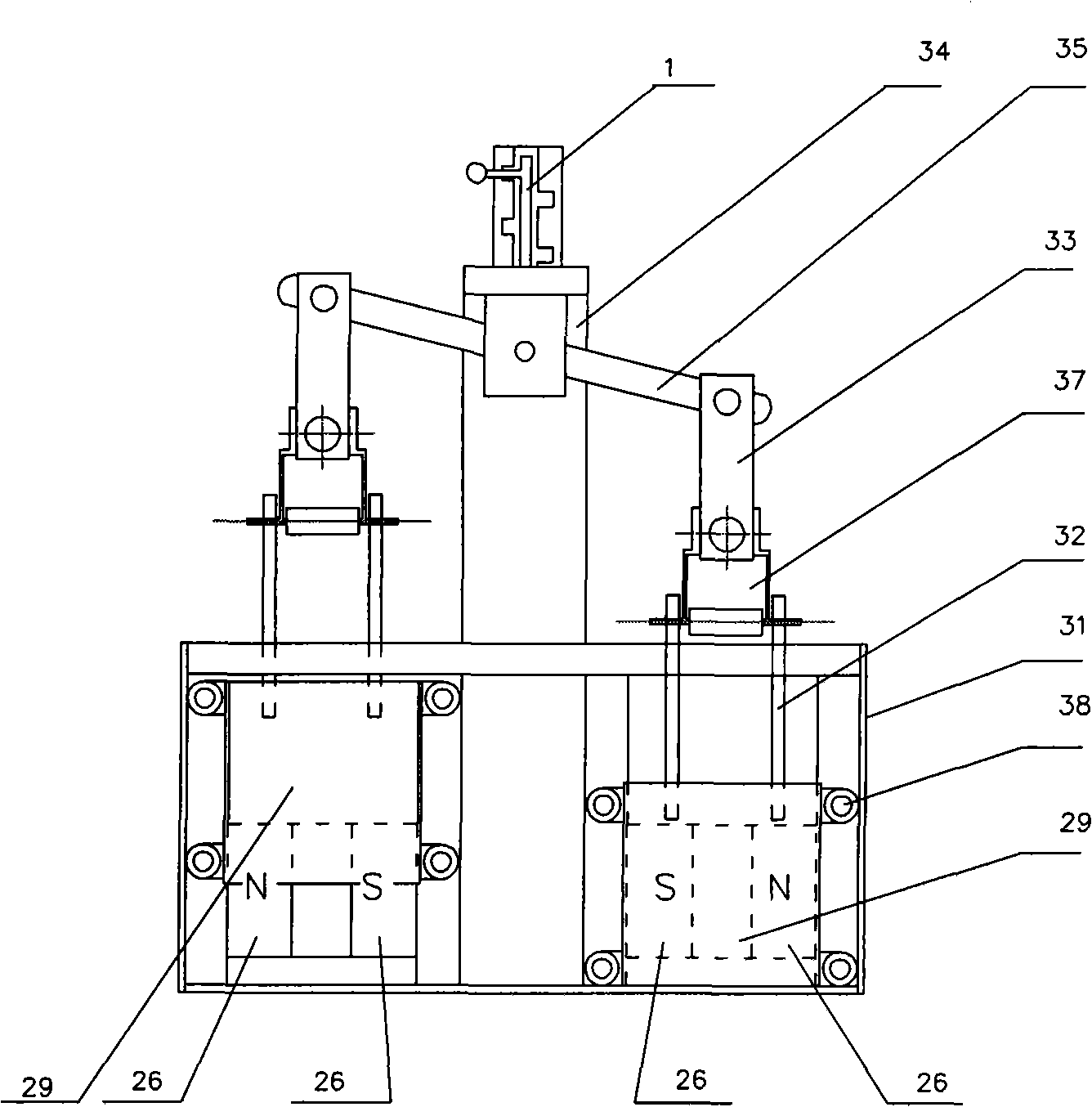
[0029] The specific implementation method (the present embodiment is a twin-cylinder engine)

[0030] 1. Install two hoof-shaped strong magnets and accessories on the middle and lower parts of the two pendulums respectively to form two magnetic pendulum assemblies. The magnetic pendulum is installed in the pendulum frame with the pendulum pin so that the magnetic pendulum can Swing back and forth. The backs of the middle and lower parts of the two pendulums are respectively connected to a "bow-shaped connecting rod" with connecting rod pins, and the connecting rods are respectively connected to the two ratchet wheels of the ratchet shaft with ratchet connecting rod pins.

[0031] 2. Install the other two hoof-shaped strong magnets and accessories in parallel in the suction seat frame to form a "magnetic suction seat" assembly. A switch slot is left in front of the poles of the two magnets, and a movable magnetic isolation plate assembly is installed in each slot as a disconne...


PUM


Abstract

The invention provides a 'ratchet swinging magnetic engine' and belongs to the field of engines. The engine adopts a permanent magnet to replace fuel and energy for doing work so as to protect environment. The application proposal comprises: two U-shaped kicker magnets form a magnetic holder (a fixed magnet); the magnetic holder attracts two magnetic swing hammers which are arranged in a swing hammer frame and made of two U-shaped kicker magnets through opposite poles to complete the power doing process; the magnetic swing hammers (a movable magnet) are connected with a ratchet by arc-shaped connecting rods and are driven by gears arranged on a ratchet shaft, a flywheel shaft and a cam shaft; the cam wheel drives a switch swinging arm to drive magnetically shielding switches to prevent the magnetic force between the fixed magnet and the movable magnet; two groups of cushioning and counteracting springs, extension springs and limiting springs, which are arranged under a swinging hammer, complete a reset stroke. The fixed magnet and the movable magnet operate in an alternating way under the control of the switching levers of two specially-made magnetic shielding switches to allow the two magnetic swing hammers to swing circularly and repeatedly so as to complete the power doing and reset stroke. Power output is realized through the constant torque output of a flywheel.

Description

technical field [0001] The invention relates to a "spindle magnetic motor", which belongs to the field of engines. Background technique [0002] At present, the power machinery used in China and abroad basically needs to be supplied with traditional coal, electricity, and oil energy sources to perform work, which seriously pollutes the environment, coupled with energy shortages, so it is a never-ending subject to explore and replace traditional energy engines. For a long time, there have been many researches and inventions on magnetic motors using permanent magnetic energy, but almost none of them can be practically applied. The reasons are: ①There is no substance that can cut off the magnetic field lines of two magnets with opposite sexes and then control the on-off of their suction to perform work; ②If you use a shield The switch is cut off, the switch consumes too much energy, and the magnetic energy cannot do work; ③The switching speed is difficult to accurately control....

Claims


Application Information

Patent Timeline
Patent Type & Authority Applications(China)
IPC IPC(8): H02N11/00H02K7/06H02K7/075
Inventor 胥明山胥亚
Owner 胥明山
Why Eureka
Try Eureka