
A bushing for a main high voltage conductor

A technology for main wires and bushings, applied in the direction of voltage dividers, electrical components, lead-in/through-type insulators, etc., to achieve the effect of high voltage division ratio

Active Publication Date: 2012-12-26
HITACHI ENERGY SWITZERLAND AG
View PDF3 Cites 0 Cited by
  • Summary
  • Abstract
  • Description
  • Claims
  • Application Information

AI Technical Summary

Problems solved by technology

[0006] The invention aims to solve the problem of stopping fast high voltage transients on the main line to prevent damage to the bushing provided with the measuring tap

Method used


Image

  • A bushing for a main high voltage conductor
  • A bushing for a main high voltage conductor
  • A bushing for a main high voltage conductor

Examples


Embodiment Construction

[0024] Embodiments of the invention are discussed in detail below. In describing the embodiments, specific terminology is employed for the sake of clarity. However, the invention is not limited to these specific terms so selected. While specific exemplary embodiments are discussed, it should be understood that this is done for illustration purposes only. A person skilled in the relevant art will recognize that other components and configurations may be used without departing from the spirit and scope of the invention.

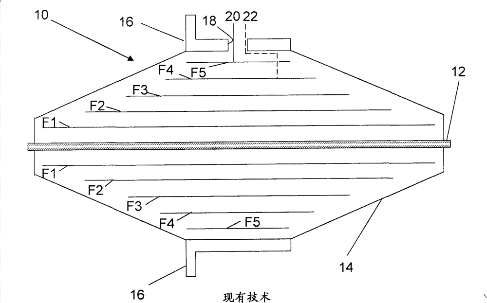
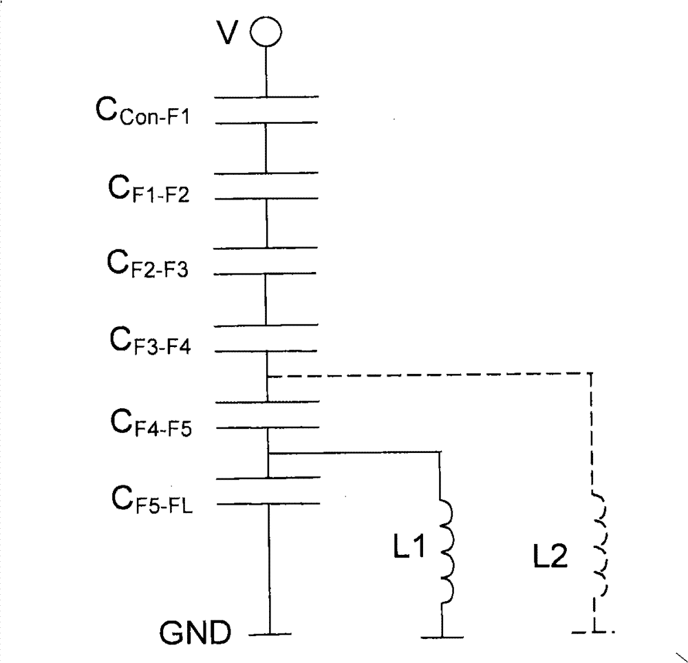
[0025] figure 1 and Figure 2 describe a prior art bushing and are therefore not described again.

[0026] Bushings for main high-voltage conductors according to the invention can be used, for example, for interconnection between electrical installations, such as for example transformers and switchgear interconnections between separate houses. The bushings can for example be arranged in the walls between the houses. It can also be provided on the housing of...


PUM


Abstract

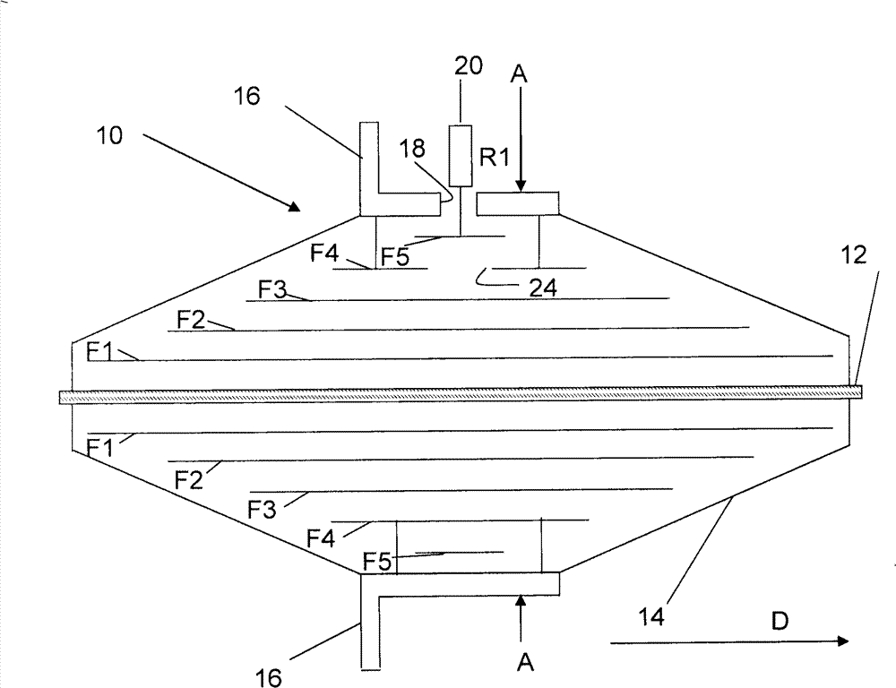
The present invention concerns a bushing (10) for a main conductor (12) comprising a number n of foils (F1, F2, F3, F4, F5) of electrically conductive material provided spaced from each other around an elongated volume stretching through the bushing and provided for the main conductor (12), and a mechanical fastening and electrical grounding body (16) encircling the foils and being provided with a measurement opening (18). The (n-1) th foil (F4) from the volume in a direction (D) perpendicular to the direction of elongation of the volume includes an opening (24) and is electrically attached to the body (16). The n th foil (F5) from the volume in the same direction, which is placed between the body (16) and the (n-1 ) th foil, is connected to a tap (20) via the measurement opening for enabling electrical measurements of the bushing. This type of bushing withstands fast high-voltage transients on the main conductor.

Description

technical field [0001] The present invention relates to electrical equipment and more particularly to bushings for main conductors of interconnected electrical equipment. Background technique [0002] Bushings for high-voltage conductors are known for interconnecting electrical installations, for example, such as are arranged in separate houses. Such bushings are then generally placed in the walls between the houses. [0003] A known such bushing for mains conductors is in figure 1 is schematically shown in , which shows a section of such a bushing taken along the length direction of the main electrical high-voltage conductor 12 . The main conductor 12 passes through the middle of the bushing, and thus the bushing 10 surrounds the main electrical conductor 12 . The main conductor 12 is furthermore radially surrounded by a number of foils F1 , F2 , F3 , F4 and F5 of electrically conductive material arranged inside the bushing 10 . In this known bushing 10 there is thus a ...

Claims


Application Information

Patent Timeline
Patent Type & Authority Patents(China)
IPC IPC(8): H02G3/04
CPCH01B17/28G01R15/06
Inventor K·约翰森
Owner HITACHI ENERGY SWITZERLAND AG
Learn More