
Self-protecting core system

a core system and self-protection technology, applied in the direction of instruments, generating/distributing signals, pulse techniques, etc., can solve the problems of receiving data, prior art systems that detect data errors typically only become aware of errors, etc., to suppress the edge of the next clock cycle, improve stability and reliability, and improve system performance

Active Publication Date: 2011-03-15
TEXAS INSTR INC
View PDF9 Cites 0 Cited by
  • Summary
  • Abstract
  • Description
  • Claims
  • Application Information

AI Technical Summary

Benefits of technology

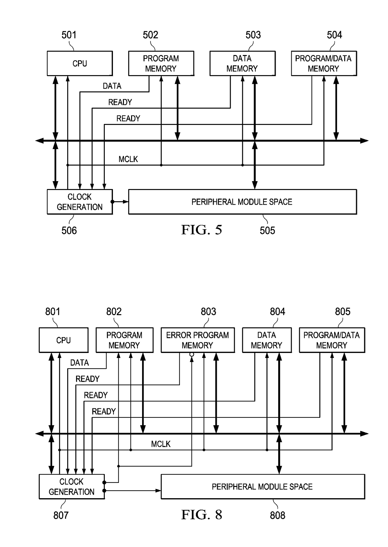
The present invention provides an electronic device with a master, a slave, and a bus for transmitting data. The device includes a clock generator that provides a system clock for the master and the slave. The clock generator determines whether the received data is correct and suppresses the edge of the next clock cycle of the system clock if the data is not correct. The clock generator allows the edge of the next clock cycle if the data is correct. The device evaluates or checks the received data on a clock cycle by clock cycle basis. The invention provides better stability and reliability by detecting incorrect data before the master receives the data and removes all possible errors or delays outside the master. The system clock frequency can be increased or decreased according to the immediate conditions and needs of the system. The invention also provides a method for generating a system clock signal.

Problems solved by technology

Any error in the received data may relate to a critical data path or a slave device which is too slow to transfer data at the system clock rate.
Prior art systems detect data errors typically only become aware of errors after the data has entered the master.

Method used


Image

  • Self-protecting core system
  • Self-protecting core system
  • Self-protecting core system

Examples


Embodiment Construction

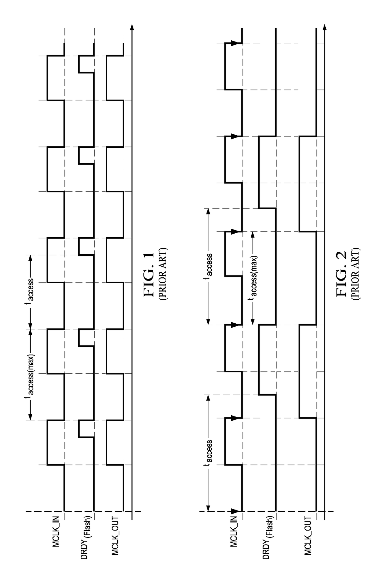
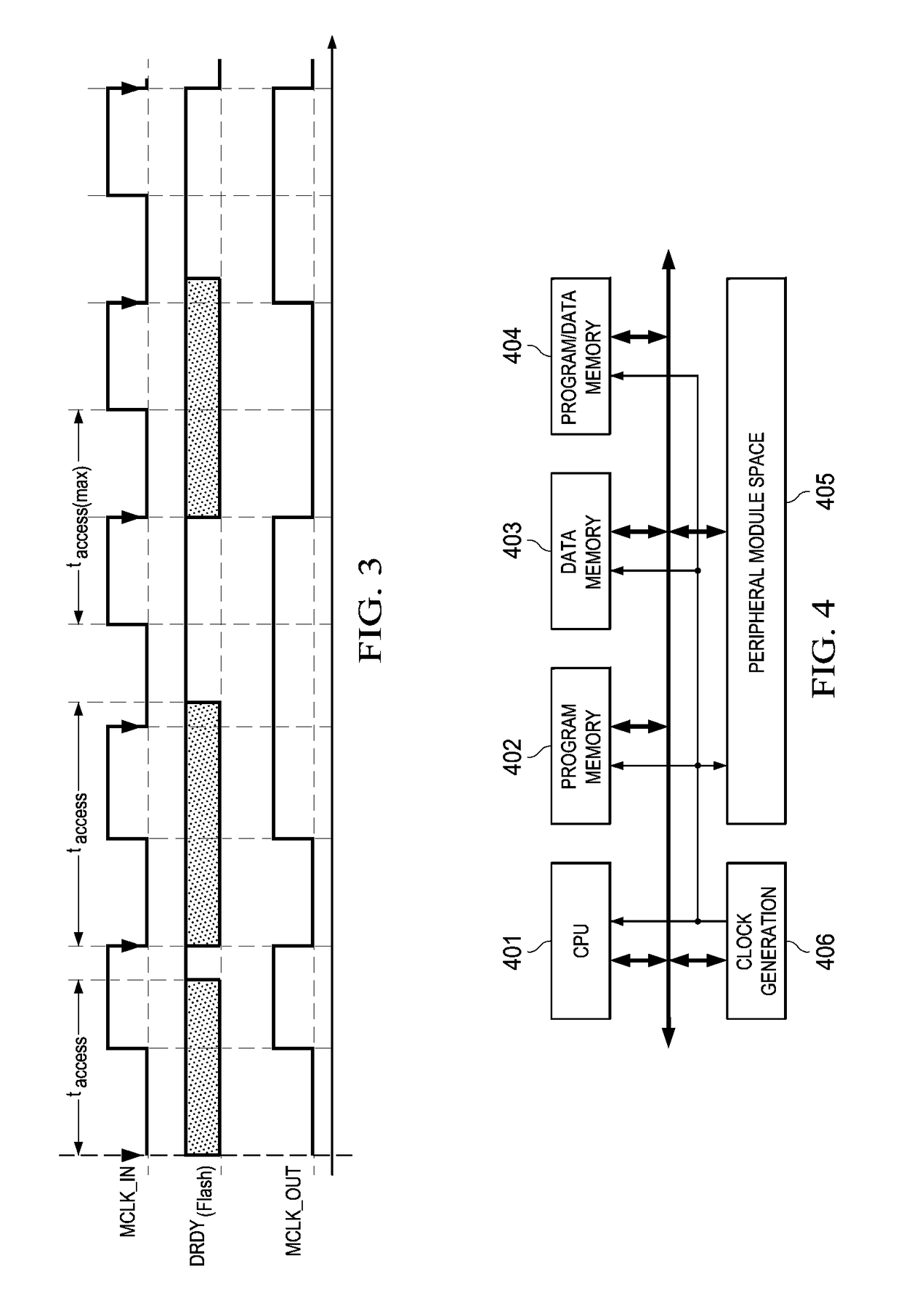
[0023]FIG. 1 illustrates waveforms of signals of a prior art electronic device including a master and a slave and a bus. In the prior art system clock MCLK_IN is used for the master and the slave without any adjustment or adaptation as system clock signal MCLK_OUT. This example assumes the slave is a flash memory which issues a data ready signal DRDY when data transfer is complete. Thus the slave itself evaluates whether the transmitted data is complete. Signal DRDY is used by the master to determine data integrity. The actual data response access time taccess of the flash memory is lower than maximum access time taccess(max) for the frequency of system clock MCLK_OUT. The master device reads the received data at a falling edge of system clock signal MCLK_OUT. Because the actual access time taccess is lower than maximum access time taccess(max), the received data is always on time and errors will not occur.

[0024]FIG. 2 illustrates waveforms of signals of a prior art system in a diff...


PUM


Abstract

The present invention is applicable to an electronic device including a master, a slave, a bus coupling the master and the slave and a clock generator for providing a system clock to the master and slave. The clock generator determines whether the received data is correct on a cycle-by-cycle basis. The clock generator suppresses an edge of a next clock cycle of the system clock signal if the data is not to be correct. The clock generator allows the edge of a next clock cycle of the system clock signal if the data is correct.

Description

CLAIM OF PRIORITY[0001]This application claims priority under 35 U.S.C. 119(a) to German Patent Application No. 10 2008 120 285.8 filed Mar. 3, 2009 and under 35 U.S.C. 119(e)(1) to U.S. Provisional Application No. 61 / 141,391 filed Dec. 30, 2008.TECHNICAL FIELD OF THE INVENTION[0002]The technical field of this invention is an electronic device comprising a master, a slave, a bus and a clock generator providing a system clock and a corresponding method.BACKGROUND OF THE INVENTION[0003]A critical part in a microcontroller system is program execution, which should never be out of control. Many deficiencies or unexpected situations can be successfully managed by protection or secure system control functions as for example the use of watchdog circuits. A critical situation which can not be handled by a watchdog circuit occurs if parts or all of the system fail to comply with the system clock frequency. In this situation a slave memory may not be able to deliver the data on time without c...

Claims


Application Information

Patent Timeline
Patent Type & Authority Patents(United States)
IPC IPC(8): H03K3/00
CPCG06F13/4291H04L7/0008
Inventor DIEWALD, HORSTZWERG, MICHAEL
Owner TEXAS INSTR INC
Learn More