Thread take-up lever structure of sewing machine

A thread take-up lever and sewing machine technology, applied in the field of sewing machine parts, can solve the problems of suture detachment, inconvenient thread entry, and detachment of sutures, etc.

Inactive Publication Date: 2009-08-26
曾贤长
View PDF0 Cites 10 Cited by
  • Summary
  • Abstract
  • Description
  • Claims
  • Application Information

AI Technical Summary

Problems solved by technology

[0002] According to the current structure of the thread take-up lever of sewing machines, there are many structures, especially for the structure that prevents the sewing thread from falling off from the thread take-up lever. This is the main improvement of the thread take-up lever. At present, relevant patent applications have been filed by the industry, such as Taiwan. Patent M249962 "Improvement of thread take-up lever structure of sewing machine to prevent thread falling off" new patent case, among which, such as Figure 8 As shown, the thread take-up lever 90 is bent as a whole, and a lead end 91 is bent above, and the lead end 91 and the body form a suture seat area 92 to prevent the suture from jumping out. The landing area 92 has a long and narrow structure, and a groove surface 910 is provided on the upper surface of the lead end 91. This groove surface 910 is used for a beam clamping piece 93 to sit and form a stop end 930. On the stop end 930 A concave arc part 931 is provided, which has the function of preventing the thread from jumping out, and one end is clamped, and the other end is open. In order to prevent the suture from easily slipping out of the suture seating area 92, this area is designed as a long and narrow space with a very small gap. shaped channel, so that the suture can prevent the suture from jumping out easily after entering; the suture seat area 92 is a long channel structure with a narrow gap. Due to the space limitation of the narrow gap, it is very difficult to completely deal with the sharp burr 920 in the channel, so it often causes inconvenience when the suture enters the channel, and the cutting or damage of the suture is caused by the sharp burr of the channel. After the thread is damaged, it is easy to be broken by the thread take-up lever during sewing, resulting in frequent thread breakage, and the thread must be re-threaded, which not only wastes time, but also seriously affects the quality of sewing
[0003] In addition, a clamping piece is provided on the thread take-up lever, and the stop end of the clamping piece is tied to the side of the lead end. There is still a considerable gap between the stop end and the lead end, and the generation of this gap cannot be completely closed. The detachment of the suture is forbidden, and there is still the possibility of suture detachment, so it is necessary to improve
[0004] In addition, the prior art part in this case includes: the prior art simply bends the end of the lead wire, and this structure still has the possibility of suture falling off. In addition, an elastic thread is positioned laterally on the end of the lead wire. The folded structure, this elastic thread structure is also a structure that laterally supports the retaining line at the end of the lead wire, and this sideward retaining line structure is still likely to cause unnecessary gaps, resulting in the absence of suture detachment, Therefore, there is a need to improve

Method used


Image

  • Thread take-up lever structure of sewing machine
  • Thread take-up lever structure of sewing machine
  • Thread take-up lever structure of sewing machine

Examples


Embodiment Construction

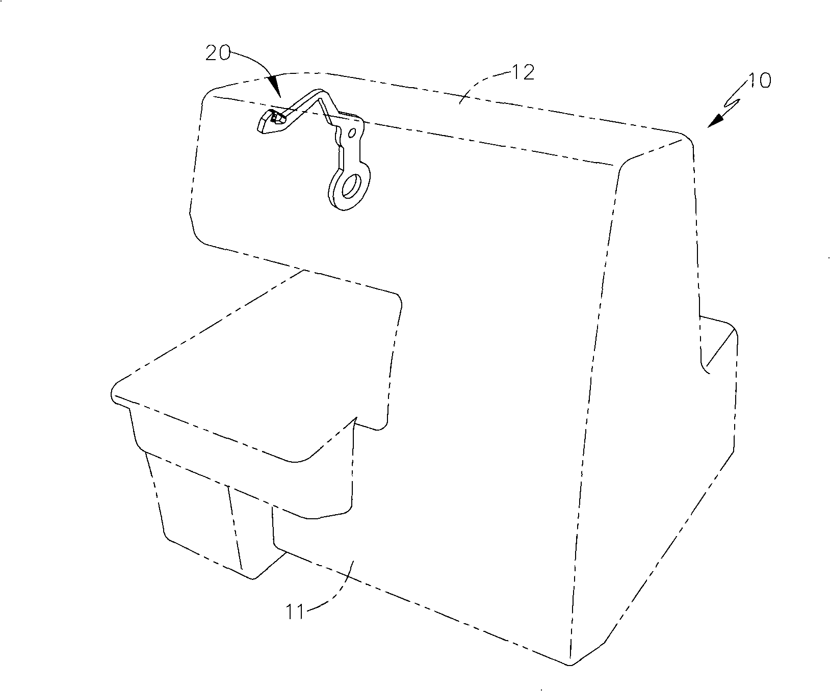
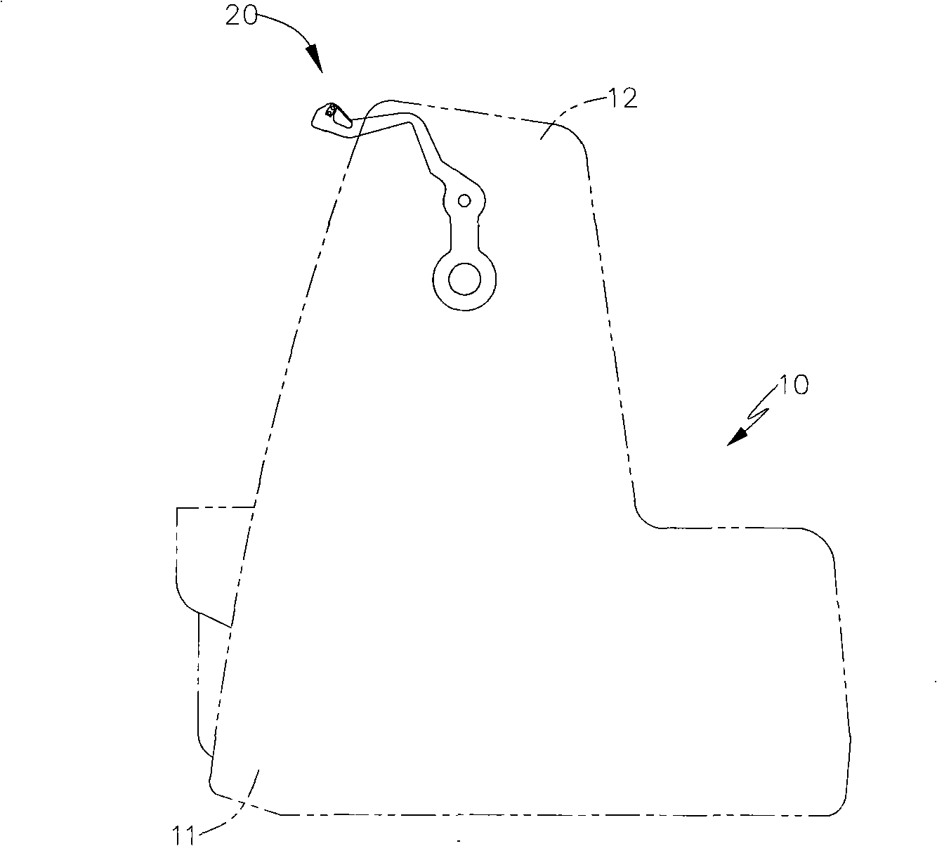
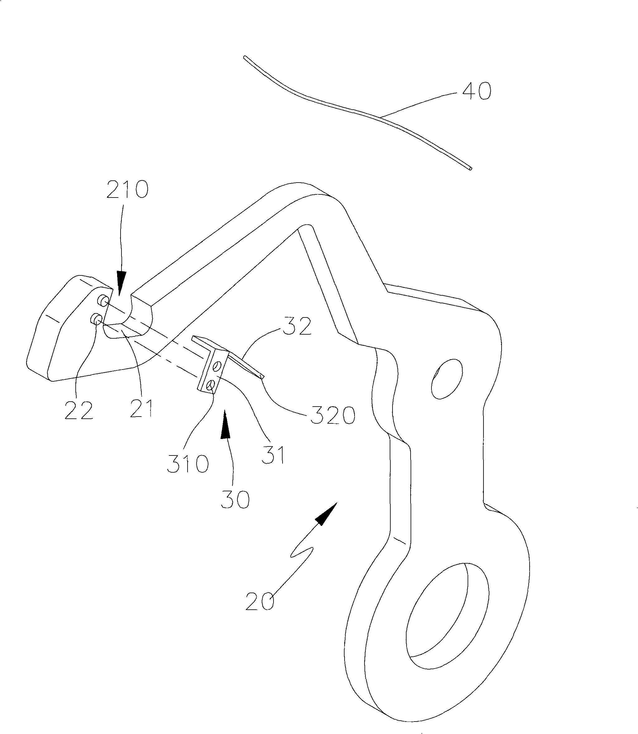
[0020] Such as figure 1 , 2 , 3, the sewing machine 10 has a machine base 11 and a cantilever 12, and a thread take-up lever 20 is additionally provided on the cantilever 12. The thread part 21 forms an open end 210 laterally, and the thread take-up lever 20 is provided with at least one positioning part 22 near the open end 210. One end of the member 30 is fixed, and the other end is bent to stop against the front of the opening end 210 of the wire holding portion 21, forming a one-way sealing structure.

[0021] The wire retaining member 30 mainly has a fixed end 31 flatly attached to the side of the thread take-up lever 20. The fixed end 31 is provided with a perforated fixed portion 310 relative to the positioning portion 22, and the fixed portion 310 is riveted through the positioning portion 22. In one body; and in the embodiment shown in the present invention, the number of the positioning part 22 and the fixing part 310 is a structural form that cooperates with each...


PUM


Abstract

The invention discloses a thread take-up lever structure of a sewing machine, in particular a thread take-up lever structure which is arranged on the sewing machine and can stop the exiting of stitches, wherein a head end of a thread take-up lever is provided with a C-shaped thread receiving part, the thread receiving part is provided with an opening end, a positioning part is arranged near the opening end for a thread retaining part to fix, one end of the thread retaining part is a fixing part which is positioned on the positioning part, while the other end is an elastic retaining part which extends into the inside of the opening end from the outside of the opening end, the other end of the retaining part is a free end and is pressed against the inner edge of the opening end, the whole retaining part is reliably sealed, and has a state of unidirectional opening and another direction closing to ensure that a sewing thread enters from an outward opening end of the thread receiving part and elastically leaves the position where the opening end is pressed through the free end of the retaining part of the thread retaining part, and the free end automatically rebounds to the position where the opening end is pressed to be immediately closed and non-returned to become a structure used for automatically stopping to prevent the thread breakage after entering the thread receiving part.

Description

technical field [0001] The invention relates to a sewing machine part, in particular to a sewing machine thread take-up lever structure. Background technique [0002] According to the current structure of the thread take-up lever of sewing machines, there are many structures, especially for the structure that prevents the sewing thread from falling off from the thread take-up lever. This is the main improvement of the thread take-up lever. At present, relevant patent applications have been filed by the industry, such as Taiwan. Patent M249962 "Improvement of thread take-up lever structure of sewing machine to prevent thread falling off" new patent case, among which, such as Figure 8 As shown, the thread take-up lever 90 is bent as a whole, and a lead end 91 is bent above, and the lead end 91 and the body form a suture seat area 92 to prevent the suture from jumping out. The landing area 92 has a long and narrow structure, and a groove surface 910 is provided on the upper su...

Claims


Application Information

Patent Timeline
Patent Type & Authority Applications(China)
IPC IPC(8): D05B49/00
Inventor 曾贤长
Owner 曾贤长
Why Eureka
Try Eureka