Radio communication system and radio communication method
A wireless communication system and wireless communication technology, applied in the field of wireless communication systems, can solve problems such as large space power attenuation, achieve the effects of efficient communication, ensure transmission speed, and fast transmission speed
- Summary
- Abstract
- Description
- Claims
- Application Information
AI Technical Summary
Problems solved by technology
Method used
Image
Examples
Embodiment 1
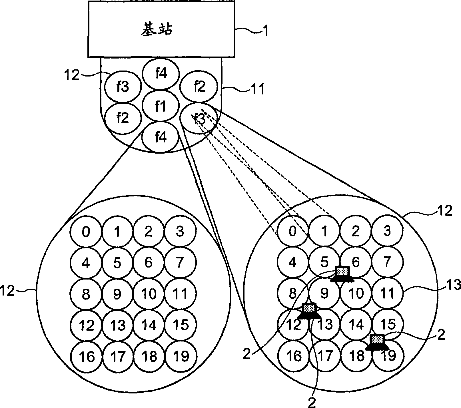
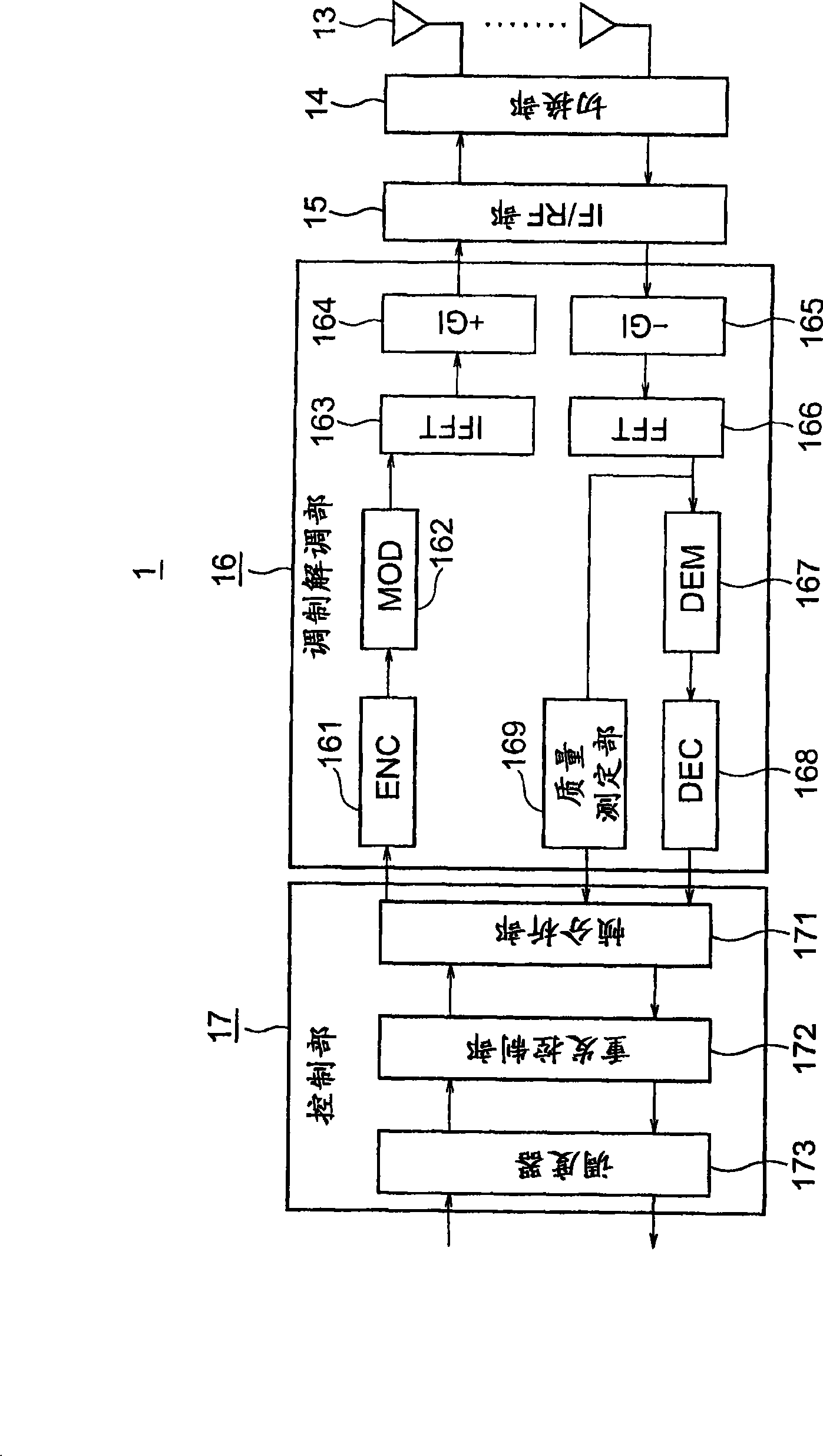
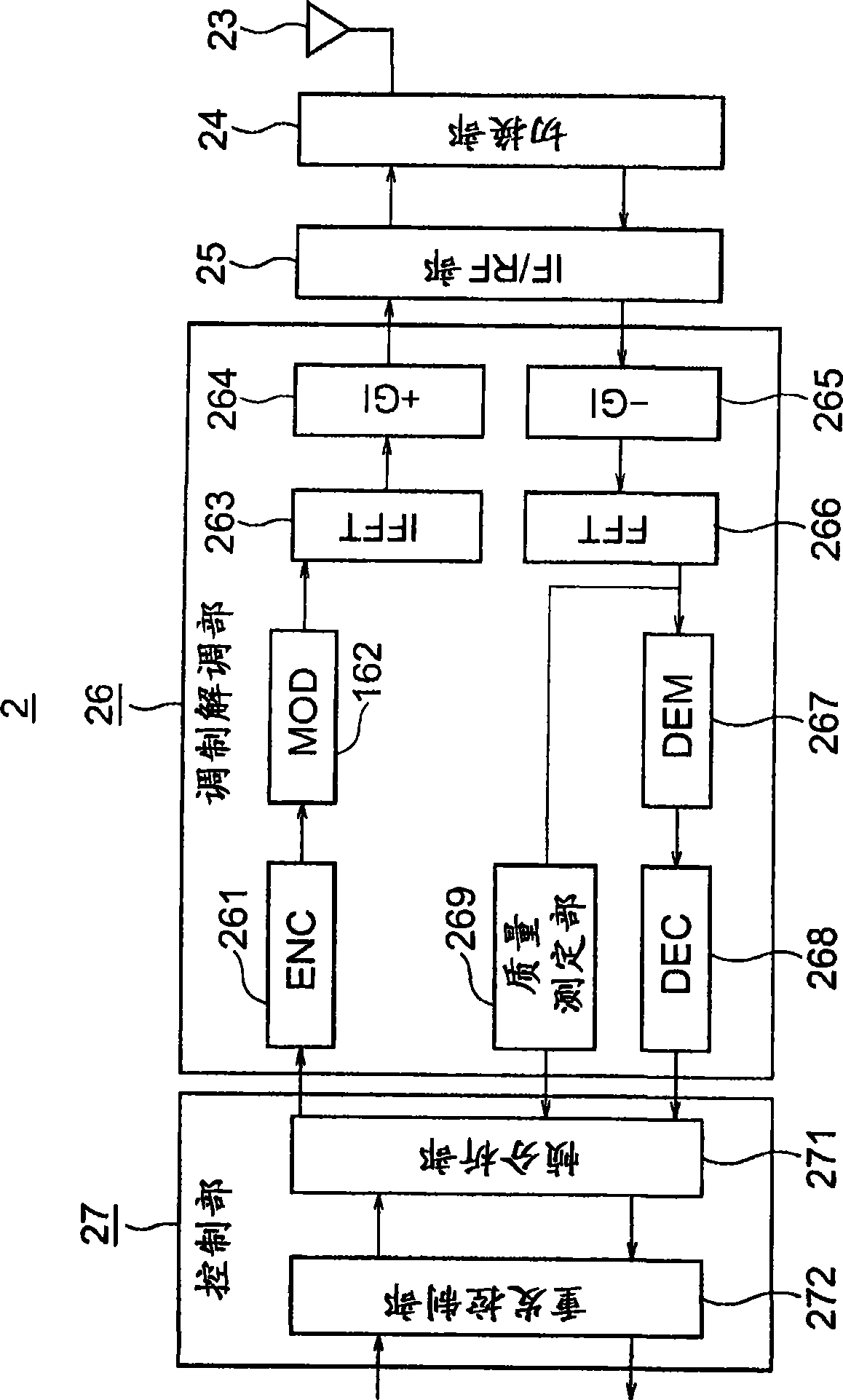
[0038] refer to Figure 1 to Figure 7 as well as Figure 10 A wireless communication system according to Embodiment 1 of the present invention will be described. figure 1 It is a diagram showing the configuration of a wireless communication system according to Embodiment 1 of the present invention. In addition, in each figure from now on, the same code|symbol represents the same or a corresponding part.
[0039] exist figure 1 In the wireless communication system of the first embodiment, a base station 1 and a plurality of (for example, three) terminals 2 are provided. A base station 1 is installed, for example, on the ceiling of a building, and a terminal 2 such as a personal computer having an antenna is installed on the floor of the building. The spatial arrangement of the base station 1 and the terminal 2 is not limited to this. The base station 1 can also be arranged on a side wall of a building. In addition, the two can be turned upside down, for example, the bas...
Embodiment 2
[0084] refer to Figure 8 A radio communication system according to Embodiment 2 of the present invention will be described. Figure 8 It is a diagram showing the frame structure of the wireless communication system according to Embodiment 2 of the present invention. In addition, the configuration of the wireless communication system of the second embodiment is the same as that of the first embodiment described above.
[0085] The base station 1 that has received the communication establishment request from the terminal 2 through the request channel (Request ch) including the antenna element number determines the connection time of the antenna element 13 based on the quality of service requested from each terminal 2, desired frequency band, communication time, etc., The connection interval determines the channel allocation time for communicating with each terminal 2 that has received the request. In addition, the base station 1 determines the modulation method and the radio ...
Embodiment 3
[0089] refer to Figure 9 A wireless communication system according to Embodiment 3 of the present invention will be described. Figure 9 It is a diagram showing an example when interference occurs between sectors in the radio communication system according to Embodiment 3 of the present invention. In addition, the configuration of the wireless communication system of the third embodiment is the same as that of the first embodiment described above.
[0090] Such as figure 1 As shown, in the case where a plurality of beam antennas 11 adopt a sector structure, by repeatedly using the same frequency in the same wireless communication area and spreading them planarly, a wider area can be formed. At this time, when the directivity of the antenna 23 used in the terminal 2 is wide-angle, even when the distance between the sectors is increased, interference may occur between the sectors.
[0091] Figure 9 (a) shows the structure of seven sectors of a plurality of beam antennas 1...
PUM
 Abstract
Description
Claims
Application Information
 - Generate Ideas
- Intellectual Property
- Life Sciences
- Materials
- Tech Scout
- Unparalleled Data Quality
- Higher Quality Content
- 60% Fewer Hallucinations
Browse by: Latest US Patents, China's latest patents, Technical Efficacy Thesaurus, Application Domain, Technology Topic, Popular Technical Reports.
© 2025 PatSnap. All rights reserved.Legal|Privacy policy|Modern Slavery Act Transparency Statement|Sitemap|About US| Contact US: help@patsnap.com


