
Overlap beams downstriker movable mould frame bridging machine

A technology of moving formwork and bridge building machine, which is applied in bridges, bridge construction, building construction, etc., can solve the problems of difficult connection between comb-shaped beams and movable doors, high force requirements for movable doors, and long construction assistance time. , to achieve the effect of reducing equipment weight and equipment cost, improving beam-making efficiency and light weight

Inactive Publication Date: 2010-12-29
浙江众磊起重设备制造有限公司
View PDF4 Cites 3 Cited by
  • Summary
  • Abstract
  • Description
  • Claims
  • Application Information

AI Technical Summary

Problems solved by technology

It has higher requirements on the force of the movable door on the main beam, and it is more difficult to connect the comb-shaped beam and movable door during construction, and the construction auxiliary time is longer
Usually, the traditional downward mobile formwork is under the condition of low pier and ultra-low pier, because the main girder structure is too high, the equipment cannot be constructed, and it is necessary to invest in a new formwork support to complete the construction task, which virtually increases the investment in equipment.

Method used


Image

  • Overlap beams downstriker movable mould frame bridging machine
  • Overlap beams downstriker movable mould frame bridging machine
  • Overlap beams downstriker movable mould frame bridging machine

Examples


Embodiment Construction

[0020] The bridge building machine of the present invention will be described in further detail below in conjunction with the accompanying drawings.

[0021] see Attachment

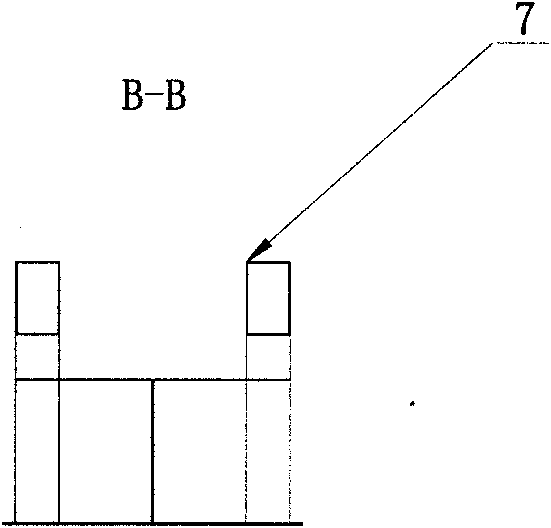
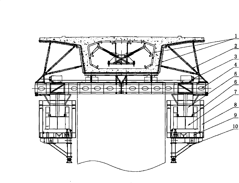
[0022] The bridge building machine is composed of main girder 5, guide beam 7, comb-shaped formwork beam 4, pier side bracket 10, trolley 9, counterweight trolley 3, hydraulic system, formwork system, etc. The bridge building machine has a symmetrical structure. There are four cars 9, two main girders 5 and two guide beams 7, eight pairs of comb-shaped beams 4, trolley 9 is arranged on the top of the bracket 10 next to the pier, and the guide beam 7 is arranged on the top of the trolley 9. 9 and the guide beam 7 is provided with a hydraulic cylinder 8, the lower end of the hydraulic cylinder 8 is fixed on the trolley 9, and the upper end is located below the load-bearing ears 12 arranged on both sides of the main beam 5, and the hydraulic cylinder 8 serves to adjust the position of the guide beam 7 , to ...


PUM


Abstract

The invention relates to a bridging device, in particular to a laminated beam descending type movable mold base bridge fabrication machine which belongs to the engineering plant. The bridge fabrication machine essentially consists of a main beam, a guiding beam, a comb shape crossbeam, a pier side bracket, a trolley, a counter weight dolly, a hydraulic system template system, etc. The guiding beam is arranged above the trolley. A hydraulic oil cylinder is arranged between the trolley and the guiding beam. The main beam is arranged in the guiding beam. A combination surface of the guiding beamand the main beam is provided with air cushions which are arranged uniformly. The movable mold base bridge fabrication machine changes the upper structure of the prior bridge fabrication machine and ensures that guiding beam and a bearing main beam form movable laminated beams, and the comb shape crossbeam can move independently when opening a mold, thereby increasing the function of the bridge fabrication machine, improving the safety, the reliability and the working efficiency of the equipment and reducing the weight and the cost of the equipment.

Description

technical field [0001] The invention relates to bridge-building equipment, in particular to a pile-beam descending mobile formwork bridge-building machine, which belongs to the category of engineering machinery. Background technique [0002] In bridge construction, the use of mobile formwork to build bridge mechanism beams has been widely used in construction. The mobile formwork bridge building machine can cast concrete at the bridge site, avoiding the one-time investment of large-scale girder transport equipment and prefabricated beam yards, and is especially suitable for complex environments such as soft foundations, deep valleys, and water. It is like a "bridge prefabrication factory" "Moving along the bridge, constructing hole by hole. The mobile formwork bridge building machine is mainly composed of main beams, guide beams, comb-shaped beams, brackets beside piers, trolleys, hydraulic systems, suspensions, formwork systems and platform walkways. [0003] The main gir...

Claims


Application Information

Patent Timeline
Patent Type & Authority Patents(China)
IPC IPC(8): E01D21/00E04G21/00
Inventor 石焕松杨晓于丙子吴振铭张连军吴林威吴晓平肖惠平
Owner 浙江众磊起重设备制造有限公司
Learn More