
Construction method for internal cooling wall and furnace liner of blast furnace

A construction method and stave technology, applied in the direction of cooling devices, internal forms, etc., can solve the problems of not meeting the requirements of engineering practice, not being able to effectively use transportation channels, and increasing costs, so as to shorten the construction period, shorten the comprehensive construction period, reduce The effect of construction costs

Inactive Publication Date: 2009-08-19
五矿二十三冶建设集团有限公司
View PDF0 Cites 27 Cited by
  • Summary
  • Abstract
  • Description
  • Claims
  • Application Information

AI Technical Summary

Problems solved by technology

In recent years, the iron and steel smelting industry has developed rapidly. The construction unit has stricter requirements on the construction period of the large (medium) repair project of the on-line blast furnace body. The contradiction between large project volume, short construction period and narrow site is particularly prominent. Meet engineering practice requirements
In the prior art, there is an installation and construction method in which the main crane is used to hoist the flange mouth of the blast furnace roof into the stave, but this is not only limited by the workload and cost of the main crane, but also limited by the work of the main crane. Due to the roof system of the blast furnace casthouse, it is impossible for the main crane hook to enter the blast furnace casthouse, so the cranes of the blast furnace casthouse and the transportation of the casthouse cannot be effectively used. channel, it is necessary to set up a cooling wall transport channel separately, which increases the cost and wastes the existing resources

Method used


Image

  • Construction method for internal cooling wall and furnace liner of blast furnace
  • Construction method for internal cooling wall and furnace liner of blast furnace
  • Construction method for internal cooling wall and furnace liner of blast furnace

Examples


Embodiment

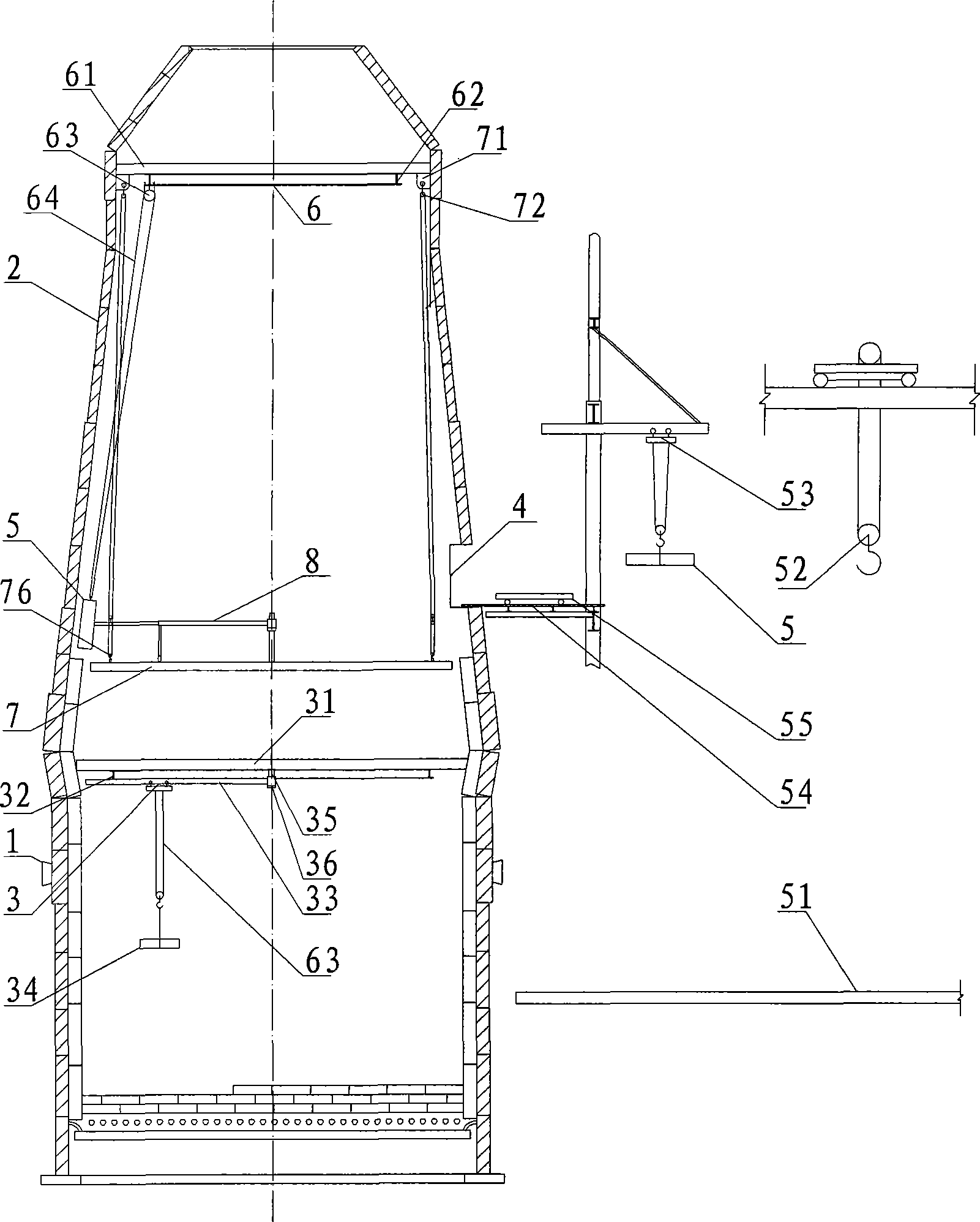
[0046] Such as Figure 1 to Figure 7 As shown, a blast furnace has a height of 40.4m (the furnace shell is a self-supporting variable-section rotating steel shell), and the on-line intermediate repair project for the blast furnace body is carried out. This project requires that the blast furnace shell 2 above the tuyere 1 be removed and updated. Stave 5 and furnace lining 34 are all dismantled and replaced, and stave 5 in the furnace altogether 16 bands (about 980t), adopt construction method of the present invention to install its stave 5 and furnace lining 34, its technological process is as follows figure 1 As shown, it specifically includes the following steps:

[0047] (1) Install furnace shell and cooling stave hoisting device: first, use a tower crane to hoist the blast furnace shell 2 from the tuyere 1 from bottom to top, and after hoisting the blast furnace straight section furnace shell 2, place the lining lifting device 3, Bosh protection shed 31 (furnace lining li...


PUM


Abstract

The invention discloses a construction method for blast furnace internal cooling wall and furnace lining. Firstly, an access opening through which the blast furnace internal cooling wall enters into an internal furnace is arranged on the furnace mantle above a blast-furnace tuyere; the cooling wall under a furnace bosh is firstly arranged by ways that a cooling wall lifting appliance arranged at the furnace throat of the internal furnace and a lifting movable swinging tray swinged in the internal furnace firstly, and a furnace bosh protection shed and a furnace lining lifting appliance are arranged at the furnace bosh secondly. Then, and the cooling wall is arranged at the top part of the furnace bosh by the cooling wall lifting appliance and the movable swinging tray, meanwhile the furnace lining construction is carried out at the lower part of the furnace bosh by a furnace lining lifting appliance and the cooling wall except for the access opening is sealed so as to complete the construction of the cooling wall of the access opening. The construction method has the advantages of low cost, convenient operation, short construction period and high construction efficiency, etc.

Description

technical field [0001] The invention belongs to the technical field of blast furnace construction, and in particular relates to a cooling wall construction method in a blast furnace major (medium) repair project. Background technique [0002] In major (medium) repair projects of blast furnaces (such as iron-making blast furnaces, etc.), the cooling staves and linings in the furnace have a large amount of construction and a long construction period, which has a decisive impact on the construction period of the blast furnace body project. Shortening the construction period is the key to ensuring the total construction period . The traditional installation method of the cooling stave is that after the installation and acceptance of the furnace shell, a scaffolding is set up in the furnace as an installation and operation platform. ~100t) for hoisting, every time a cooling stave is installed, the operation platform will be raised higher, and all cooling staves in the furnace wi...

Claims


Application Information

Patent Timeline
IPC IPC(8): C21B7/02C21B7/10
Inventor 蔡平涛张万红曹红远石艳萍
Owner 五矿二十三冶建设集团有限公司
Learn More