
Determination of battery predictive power limits

一种功率极限、极限的技术,应用在二次电池、电路、测量电等方向,能够解决没有提供解决方案、浪费燃料等问题

Inactive Publication Date: 2009-08-12
COBASYS LLC
View PDF0 Cites 28 Cited by
  • Summary
  • Abstract
  • Description
  • Claims
  • Application Information

AI Technical Summary

Problems solved by technology

However, idling the engine wastes fuel, so this does not provide an ideal solution

Method used


Image

  • Determination of battery predictive power limits
  • Determination of battery predictive power limits
  • Determination of battery predictive power limits

Examples


Embodiment Construction

[0021] The following description of preferred embodiments is merely exemplary in nature and is not intended to limit the invention, its application or uses in any way. For the sake of clarity, the same reference numbers are used in the drawings to refer to the same elements. As used herein, the term module or device means an application-specific integrated circuit (ASIC), an electronic circuit, a processor (of the shared, dedicated or grouped type) and memory, a combinational logic circuit, executing one or more software or firmware programs, and / or other suitable components that provide the described functionality.

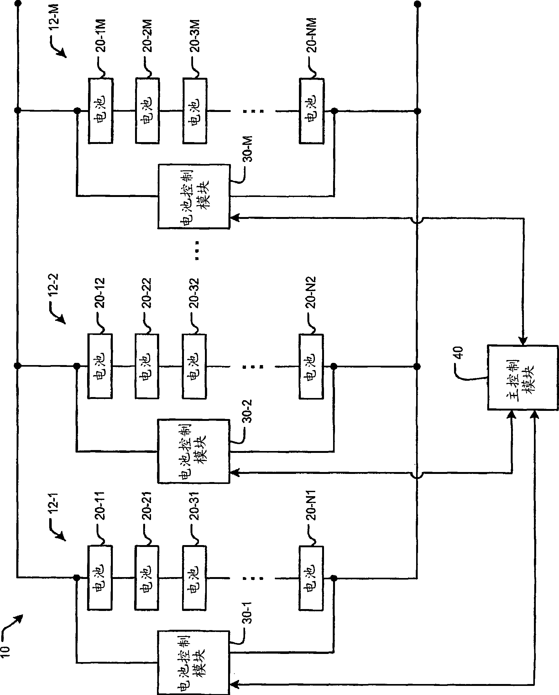
[0022] While an example system that may be used to predict the maximum power output of a battery will be shown, those skilled in the art will recognize that other systems may be used. now refer to figure 1 , the exemplary embodiment of the battery system 10 shown includes M battery subpacks 12-1, 12-2, . . . , and 12-M (collectively referred to as battery subpa...


PUM


Abstract

A battery control module for use with a battery includes a voltage measuring module that measures battery voltage and a current measuring module that measures battery current. A power limit module communicates with the current and voltage measuring modules and once every time period estimates a battery current limit that corresponds with a future time period. The battery current limit is based on a predetermined voltage limit of the battery and a battery current and a battery voltage that correspond with a time period that precedes the future time period.

Description

technical field [0001] The present invention relates to battery systems, and more particularly to determining power delivery limits for battery systems. Background technique [0002] Battery systems can be used to provide electrical energy in a wide variety of applications. Exemplary transmission applications include hybrid electric vehicles (HEV), electric vehicles (EV), heavy duty vehicles (HDV), and automobiles with 42 volt electrical systems. Exemplary stationary application systems include backup power supplies for telecommunications systems, uninterruptible power supplies (UPS), and distributed generation applications. [0003] Examples of the types of batteries used include nickel metal hydride batteries (NiMH), lead acid batteries, and other types of batteries. A battery system may include multiple battery subpacks connected in series and / or in parallel. A battery pack may include multiple batteries connected in parallel and / or in series. [0004] Inherent proper...

Claims


Application Information

Patent Timeline
Patent Type & Authority Applications(China)
IPC IPC(8): G01R31/36
CPCY02E60/12H01M10/441G01R31/3624G01R31/3675G01R31/3648G01R31/374G01R31/3842Y02E60/10
Inventor 罗伯特·J·梅利查
Owner COBASYS LLC
Learn More