
Switching unit

A switch unit and switch device technology, which can be used in protection switches, parts of protection switches, operation/release mechanisms of protection switches, etc., and can solve problems such as high costs

Inactive Publication Date: 2009-08-05
SIEMENS AG
View PDF0 Cites 5 Cited by
  • Summary
  • Abstract
  • Description
  • Claims
  • Application Information

AI Technical Summary

Problems solved by technology

However, the purchase of such a mains protection switch requires high costs
In addition to this it may be possible to use electronic devices, but so far they have not been marketed due to their high cost

Method used


Image

  • Switching unit
  • Switching unit
  • Switching unit

Examples


Embodiment Construction

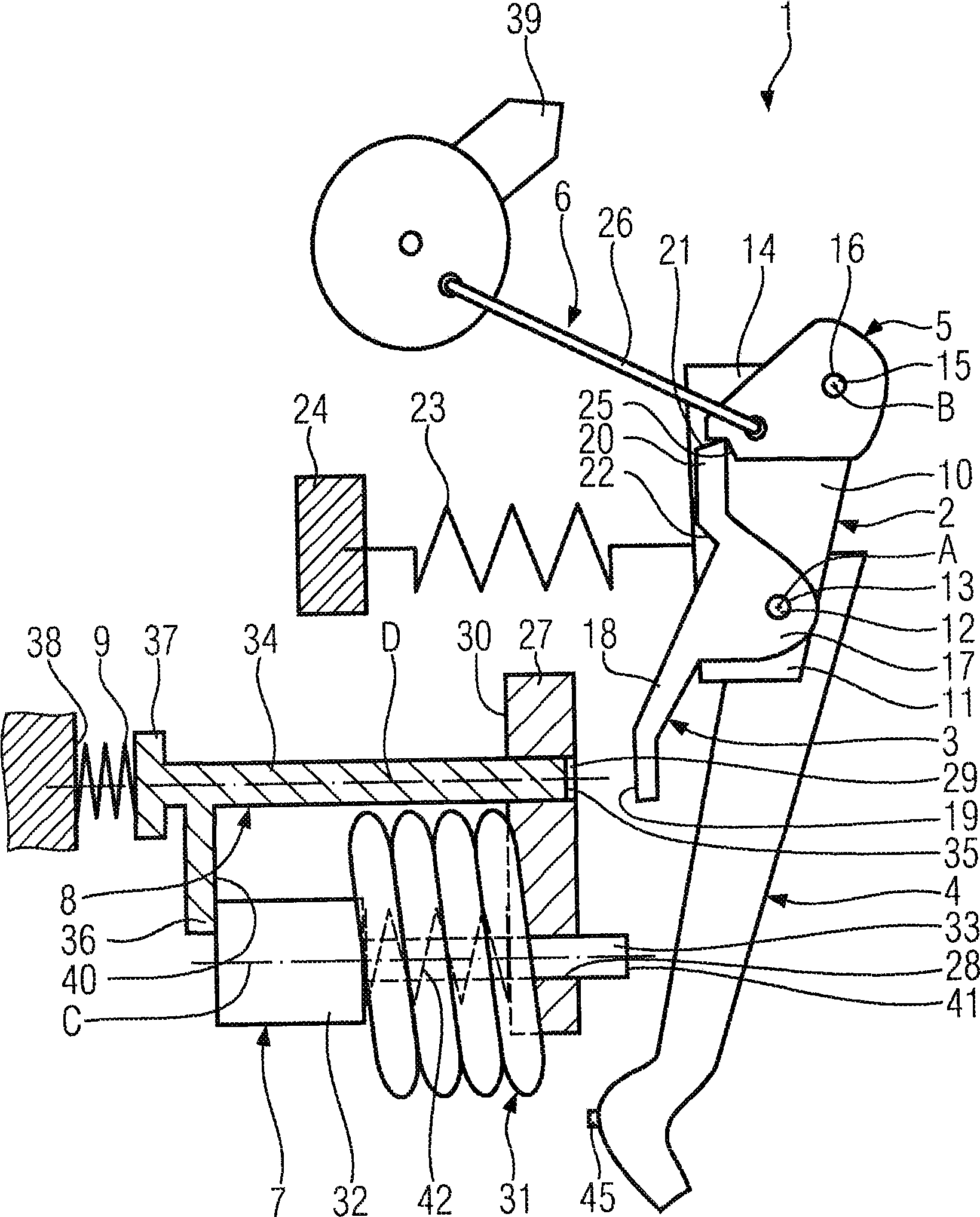
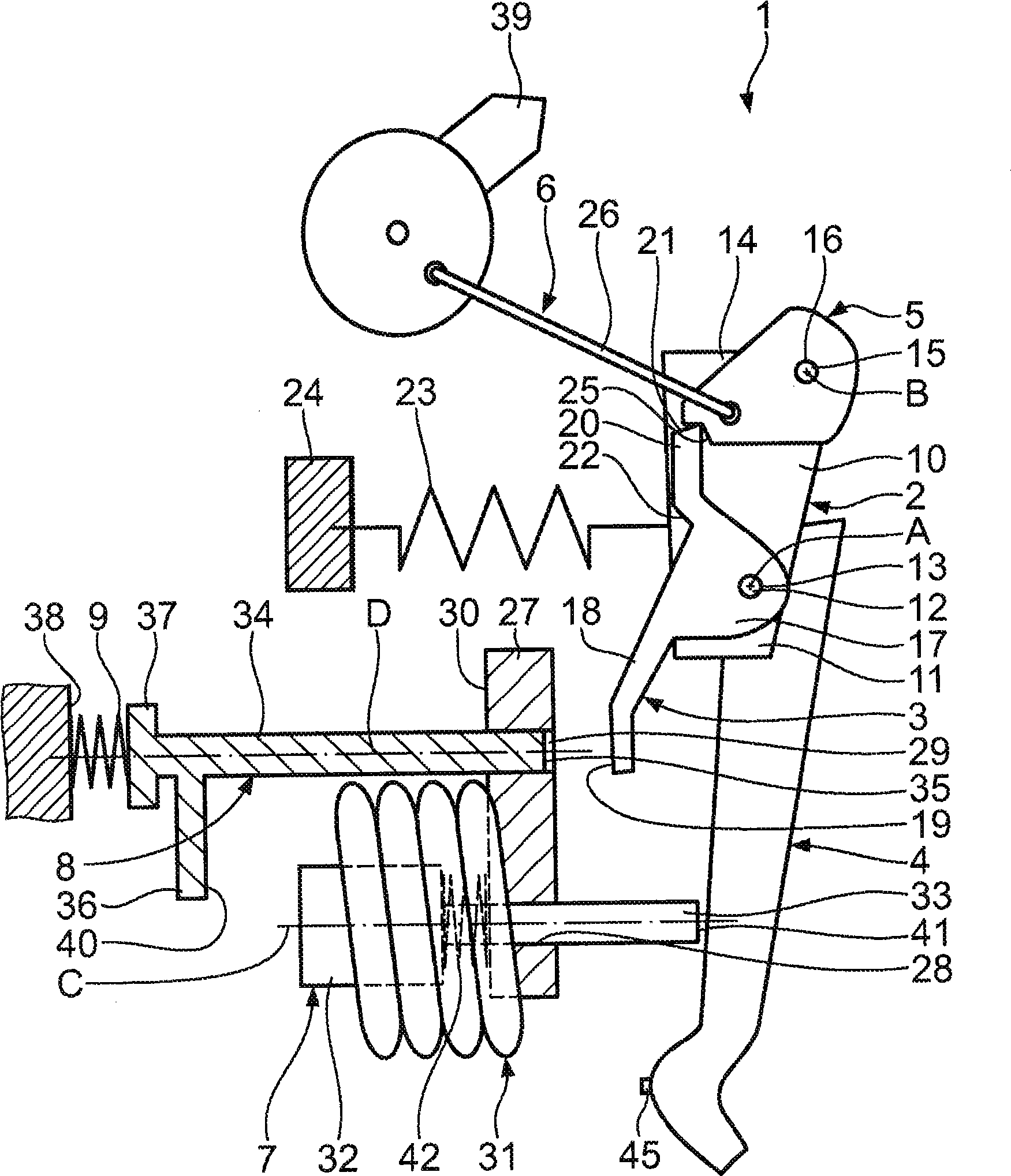
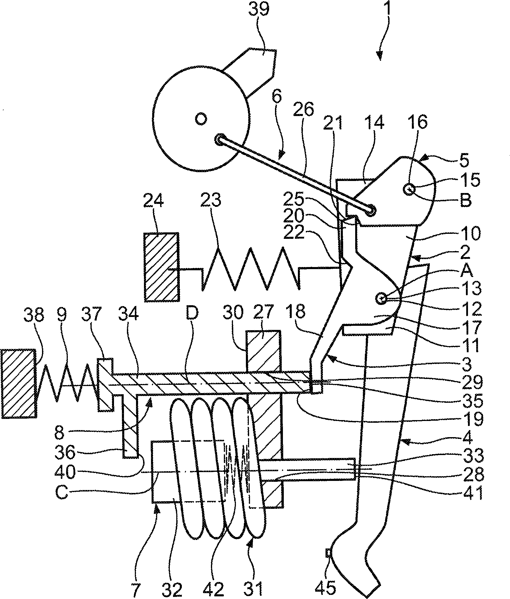
[0010] Refer below Figure 1 to Figure 3 A first embodiment of the present invention will be described. The switching device comprises a self-closing switching unit 1 according to the invention, the output of which is connected to a plurality of cable lines. In each cable path there is another switching unit which switches itself on, after which the subscribers are in each case connected. These users are generally standard architectural equipment.

[0011] The upstream switching unit 1 comprises a support plate 2 on which a release lever 3 , a contact arm 4 and a pawl 5 are pivotably mounted. The support plate 2 , the release lever 3 and the pawl 5 are components of the locking mechanism 6 . The contact arm 4 is designed larger than the release lever 3 .

[0012] Furthermore, the switching unit 1 comprises a steerable strike armature 7 and a movably mounted release pin 8 which abuts against the strike armature 7 . In the normal, uninterrupted operating state of the switch...


PUM


Abstract

The invention relates to the switching unit for the selective switching off of at least one consumer, having at least one contact point with a moveably mounted contact lever (4), an actuable hammer armature (7) for opening of the contact point by moving of the contact lever (4) and a switching lock (6) with a moveably mounted latch (5) and a moveably mounted tripping lever (3) being assigned to the latch (5). The tripping lever (3) is moveable between a latch-release-position and a latch-locking-position. The release of the latch (5) by the tripping lever (3) is time-delayed compared to the actuation of the contact lever (4) by the hammer armature (7).

Description

technical field [0001] The invention relates to a switching unit for selectively disconnecting at least one subscriber. Background technique [0002] In the case of cascading of line protection switches or circuit breakers, selectivity is decisive. In the event of a fault, only the protective means at the point closest to the fault should be switched off. It is thus possible to deactivate only the branch in question in the event of a fault. For this purpose, a selective mains circuit breaker is known from the prior art. However, purchasing such a mains protection switch requires high costs. Alternatively, electronic devices could possibly be used for this, but have so far been unable to be brought to the market due to their high cost. Contents of the invention [0003] The object of the present invention is to overcome these disadvantages of the prior art. [0004] This object is achieved by the features stated in claim 1 . The essence of the invention is that the re...

Claims


Application Information

Patent Timeline
IPC IPC(8): H01H71/24H01H71/34
CPCH01H71/34H01H71/2409H01H71/2463
Inventor 鲁德维格·比克尔托马斯·里茨尔克里斯托夫·韦伯
Owner SIEMENS AG
Learn More