
Internal combustion engine

A technology of internal combustion engine and lift, applied in mechanical equipment, engine components, engine control, etc., can solve problems such as exhaust valve vibration, and achieve the effect of simple structure and reduced vibration

Inactive Publication Date: 2009-08-05
DAIMLER AG
View PDF0 Cites 0 Cited by
  • Summary
  • Abstract
  • Description
  • Claims
  • Application Information

AI Technical Summary

Problems solved by technology

This can cause problems with the vibration of the open exhaust valve

Method used


Image

  • Internal combustion engine
  • Internal combustion engine
  • Internal combustion engine

Examples


Embodiment Construction

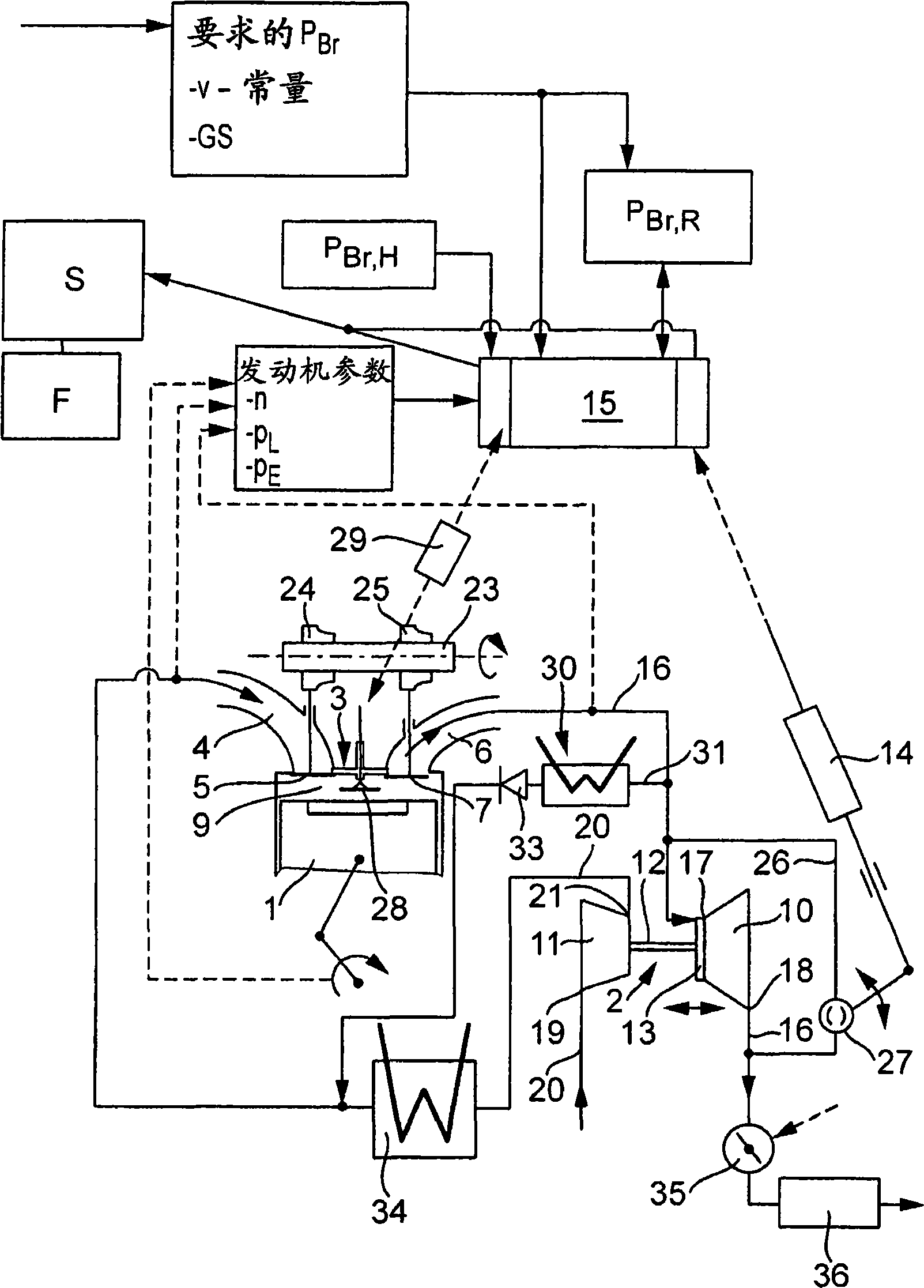
[0016] figure 1 An internal combustion engine such as a diesel engine or a spark ignition engine is shown. The enlarged view shows cylinder 1 of the internal combustion engine, the combustion chamber 9 of which is fluidly connected to intake channel 4 via intake valve 5 and to exhaust manifold 6 via exhaust valve 7 . The intake channel 4 belongs to the intake system 20 of the internal combustion engine, while the exhaust manifold 6 is connected to the exhaust line 16 of the internal combustion engine. When the intake valve 5 is opened, the combustion air flows into the combustion chamber of the cylinder 1 through the intake passage 4, and when the exhaust valve 7 is opened, the gas in the combustion chamber is discharged to the exhaust system through the exhaust manifold 6 Or exhaust line 16.

[0017] A camshaft 23 is provided for controlling the gas exchange valves 5 and 7 , on which camshafts 24 and 25 are arranged, wherein the cam 24 is assigned to the intake valve 5 and ...


PUM


Abstract

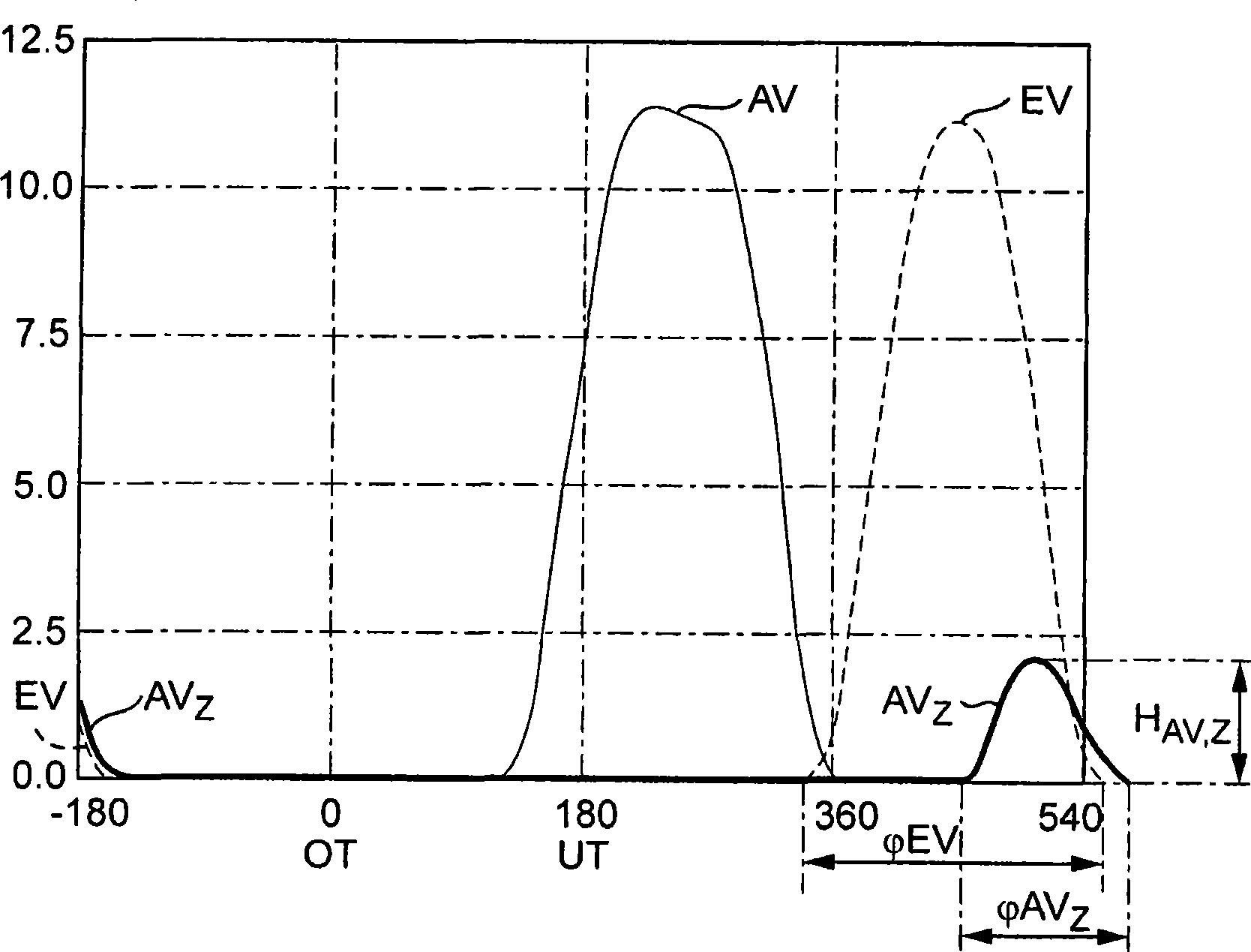
An internal combustion engine has a camshaft (23) which acts on inlet and outlet valves (5, 7), wherein the lift curve (EV, AV) of the inlet and outlet valves (5, 7) is determined by the shape of the cams (24, 25) of the camshaft (23). Arranged on the camshaft (23) is an additional auxiliary cam which acts on the outlet valve (7), as a result of which a phase-offset auxiliary lift curve (AVz) is imparted to the outlet valve (7).

Description

technical field [0001] The invention relates to an internal combustion engine according to the preamble of claim 1 . Background technique [0002] AT 408 129 B discloses a supercharged internal combustion engine whose exhaust turbine is equipped with a variable turbine geometry for variably adjusting the effective turbine inlet cross-section. In order to be able to generate high braking power during engine braking operations, the variable turbine geometry is adjusted to a blocking position with a reduced cross-section, resulting in a high exhaust gas backpressure / counterpressure against which the cylinders of the internal combustion engine must resist Exhaust back pressure to do discharge work / exhaust work. If braking power is required in the current driving conditions, it is first applied by engine braking according to AT 408 129 B. [0003] During engine braking operation, the throttle valve is in an open position so that the cylinder contents are expelled into the exhau...

Claims


Application Information

Patent Timeline
Patent Type & Authority Applications(China)
IPC IPC(8): F01L13/06
CPCF01L13/06Y02T10/12F02D13/04F02D9/08
Inventor D·贝姆M·艾弗勒S·萨姆瑟
Owner DAIMLER AG
Learn More