
Z source semi-bridge inverter

A half-bridge inverter, inverter bridge technology, applied in the direction of irreversible AC power input conversion to DC power output, etc., can solve the problems of increasing power transfer switching loss, increasing control complexity, etc., to achieve high reliability, restraint The effect of current mutation

Inactive Publication Date: 2009-08-05
SOUTH CHINA UNIV OF TECH
View PDF0 Cites 8 Cited by
  • Summary
  • Abstract
  • Description
  • Claims
  • Application Information

AI Technical Summary

Problems solved by technology

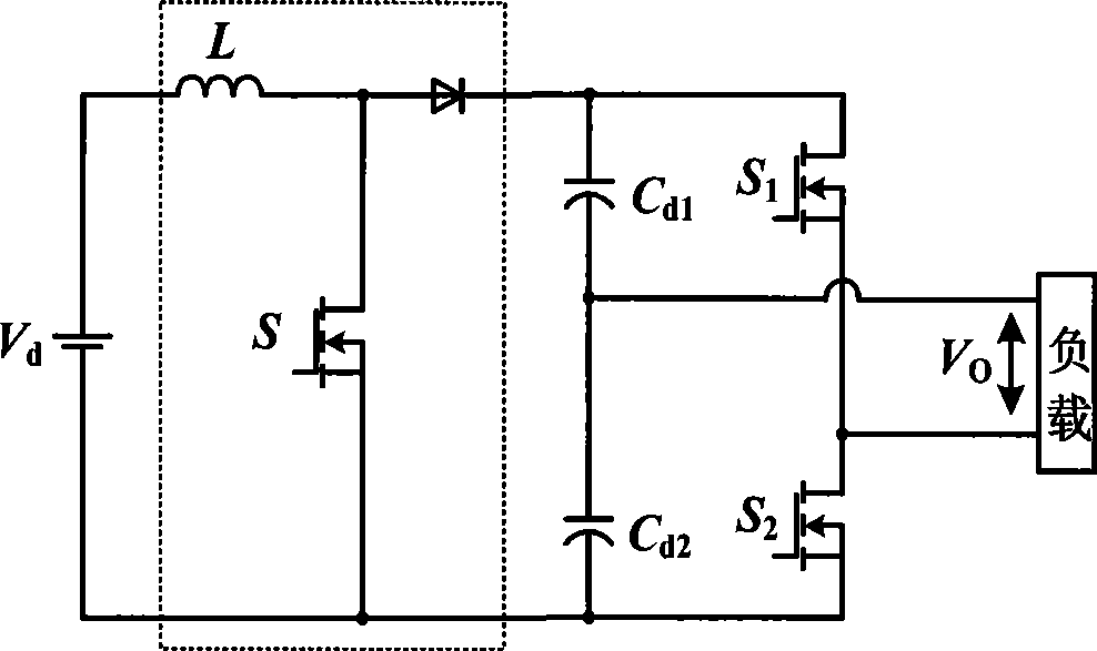
In the scheme of adding a boost link in the front stage of the inverter, at least one more switching tube is required, which increases the switching loss in power transmission and also increases the complexity of control
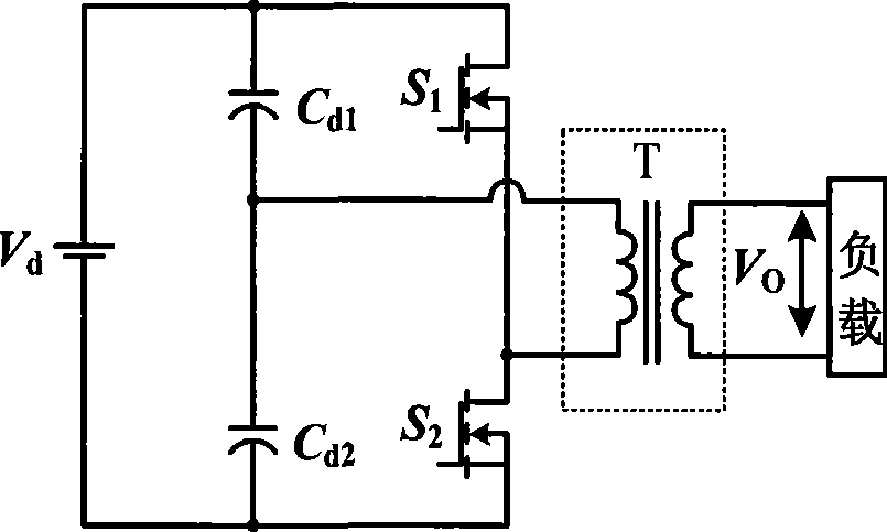
Although connecting a transformer at the output end of the inverter can increase the amplitude of the output voltage, when the transformer turns ratio is fixed, the amplitude of the output AC voltage is a certain value.

Method used


Image

  • Z source semi-bridge inverter
  • Z source semi-bridge inverter
  • Z source semi-bridge inverter

Examples


Embodiment Construction

[0013] The implementation of the present invention will be further described below in conjunction with the accompanying drawings.

[0014] refer to image 3 , capacitance C d1 、C d2 , switch tube S 1 , S 2 , forming a conventional half-bridge inverter. Capacitance C 1 、C 2 , inductance L 1 , L 2 , forming the Z source impedance. Diode D, which is used to block the current of Z source impedance from flowing back to the power supply. Inductance L 1 One end of the capacitor C 2 One end of the connection, and then with the switch tube S 1 drain connection. Inductance L 2 One end of the capacitor C 1 One end of the connection, and then with the switch tube S 2 source connection. Inductance L 2 The other end of the capacitor C 2 The other end of the connection, and then with the capacitor C d2 one end of the DC power supply V d the negative connection. Inductance L 1 the other end of the capacitor C 1 The other end of the connection, and then connected to the...


PUM


Abstract

The invention provides a Z-source half-bridge inverter, comprising a DC voltage source and a half-bridge inverter which consists of two stored energy capacitors and two switch tubes; the Z-source half-bridge inverter also comprises a diode (D) and a Z-source impedance; the Z-source impedance is connected in parallel between the two inverter bridge arms of the half-bridge inverter and two ends of the DC voltage source; the diode (D) is used for blocking the current of the Z-source impedance from flowing back in the voltage source. The Z-source impedance avoids the damage due to the direct conduction of a first switch tube and a second switch tube; and the first switch tube and the second switch tube have a boost function when being conducted simultaneously. The duty cycle of the first switch and the second switch tube can be controlled to realize the buck or boost of the inverter, thus realizing the output of symmetric or asymmetric amplitude of positive and negative pulse waveform. The Z-source half-bridge inverter has high reliability, wide output voltage range and abundant output AC pulse waveform, and is especially suitable for electrochemical power devices such as electroanalysis devices and electroplating devices.

Description

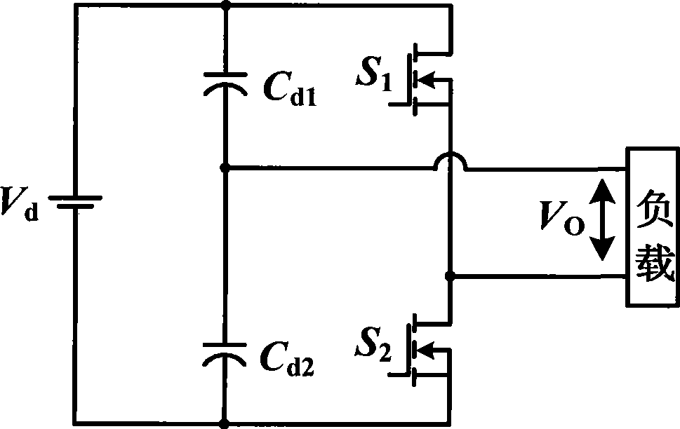
technical field [0001] The invention relates to the technical field of half-bridge inverters, in particular to a Z-source half-bridge inverter. Background technique [0002] Conventional half-bridge inverters such as figure 1 As shown, the inverter bridge arm is directly connected in parallel with the DC voltage source. When the upper and lower switch tubes of the inverter bridge arm are directly connected due to false triggering, a very large current will flow and the switch tube will be damaged. Moreover, the amplitude of the output AC voltage of this type of half-bridge inverter is only half of the input voltage, which belongs to the step-down inverter, and the output voltage range is relatively narrow. In order to increase the amplitude of the output AC voltage, the traditional method is to add a boost link in the front stage of the inverter, or connect a transformer at the output end to boost the voltage, such as Figure 2a and Figure 2b shown. In the scheme of add...

Claims


Application Information

Patent Timeline
IPC IPC(8): H02M7/12
Inventor 张波肖文勋张桂东
Owner SOUTH CHINA UNIV OF TECH
Learn More