Electricity-saving radio frequency alarm device

An alarm device and a power-saving technology, applied in the field of power-saving radio frequency alarm devices, can solve the problems of increasing the volume and weight of the battery, unable to function powerfully, unable to meet the requirements of use detection, etc., and achieve the effect of reducing power consumption

Inactive Publication Date: 2009-08-05
广州天绛智能科技有限公司
View PDF0 Cites 4 Cited by
  • Summary
  • Abstract
  • Description
  • Claims
  • Application Information

AI Technical Summary

Problems solved by technology

[0002] Wireless radio frequency technology is more and more used in the application environment of personnel and object identification and positioning. The basic function of the original 2.4G active electronic tag is that the radio frequency chip regularly sends out a signal of several bytes, and the reading sensor Receive this signal to determine the instant information of people and objects, but because the radio frequency tag is an active device, it must carry a battery in actual use, and in order to prolong the use of the electronic tag, it is undoubtedly necessary to increase the battery life. Size and weight, the existing power-saving mode is mainly realized by transmitting a signal for a short time and stopping the transmission for a long time. For example, the original signal transmission interval is 1 second to transmit once. If the time interval of transmitting signal is extended to 10 seconds to transmit once , the life of the battery can be extended by more than 10 times, but if it is fired once every 10 seconds, in many cases, there is no way to know the instant information of people and objects, and it cannot meet the requirements of use detection
Although people have thought of many ways to save power, such as: software and hardware materials, they can't make powerful and small

Method used


Image

  • Electricity-saving radio frequency alarm device
  • Electricity-saving radio frequency alarm device

Examples


Embodiment Construction

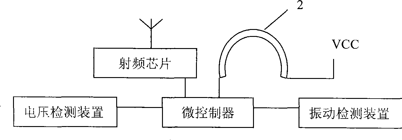
[0013] Such as figure 1 As shown in , the present invention includes a main body 1 and a buckle 2, the main body is provided with a radio frequency transceiver control circuit, the conductive metal buckle 2 is connected to the main body 1, and is connected in series in the radio frequency transceiver control circuit, so Said metal buckle 2 can adopt the wire rope of soft body, is provided with metal connector 3 on metal buckle 2. The metal connector 3 is provided with an internal thread, and the metal buckle 2 connected to the metal connector is correspondingly provided with an external thread, and the metal buckle is opened or closed through the metal connector , it is convenient to hang on people or objects.

[0014] The radio frequency transceiver control circuit such as figure 2 As shown in , it is mainly composed of a microprocessor, a radio frequency chip connected to the microprocessor, a vibration detection device, and a voltage detection device. The metal buckle 2 ...


PUM


Abstract

The invention relates to the RFID (Radio Frequency Identification) field, in particular to a power saving radio frequency (rf) alarm device, which comprises a body and a snap ring. The body is provided with an rf receiving and transmitting control circuit therein, which comprises a microprocessor that is connected with a vibration detection device. The invention uses the vibration detection device to detect the activity state of people or articles; when no movement happens, the rf receiving and transmitting control circuit transmits an rf signal at a longer time interval to reduce the energy consumption thereof; when the detection device detects a movement happens, and the rf receiving and transmitting control circuit sends out an rf signal at a shorter time interval and reports the current situation of people or articles in time. Therefore, on condition of ensuring the monitoring quality, the service life of battery can be prolonged by 7-10 times more than before.

Description

technical field [0001] The invention relates to the field of radio frequency identification, in particular to a power-saving radio frequency alarm device. Background technique [0002] Wireless radio frequency technology is increasingly used in the application environment of personnel and object identification and positioning. The basic function of the original 2.4G active electronic tag is that the radio frequency chip regularly sends out a signal of several bytes, and the reading sensor Receive this signal to determine the instant information of people and objects, but because the radio frequency tag is an active device, it must carry a battery in actual use, and in order to make the use of the electronic tag relatively prolong, it is undoubtedly necessary to increase the power of the battery Size and weight, the existing power-saving mode is mainly realized by transmitting a signal for a short time and stopping the transmission for a long time. For example, the original s...

Claims


Application Information

Patent Timeline
IPC IPC(8): G08B25/10G08B29/02G06K7/00
Inventor 郭岳衡
Owner 广州天绛智能科技有限公司
Why Eureka
Try Eureka