Plane rotational flow generator

A swirl generator and plane technology, applied in the direction of fluid flow, mechanical equipment, etc., can solve the problems of unable to form swirl, complex structure, etc., and achieve the effect of convenient manufacture, simple composition and structure, and convenient adjustment

Inactive Publication Date: 2009-08-05
XIAMEN UNIV
View PDF2 Cites 4 Cited by
  • Summary
  • Abstract
  • Description
  • Claims
  • Application Information

AI Technical Summary

Problems solved by technology

[0007] The purpose of the present invention is to solve the complex structures of some existing generating devices capable of forming swirling flow, which cannot form swirling flows parallel to planes or object surfaces, but the vortex generators that can control the boundary layer flow It can achieve the purpose, but it also has negative effects on the non-separated flow. A planar swirl generator with a relatively simple structure that can form swirl parallel to the plane or the surface of the object is provided.

Method used


Image

  • Plane rotational flow generator
  • Plane rotational flow generator
  • Plane rotational flow generator

Examples


Embodiment 1

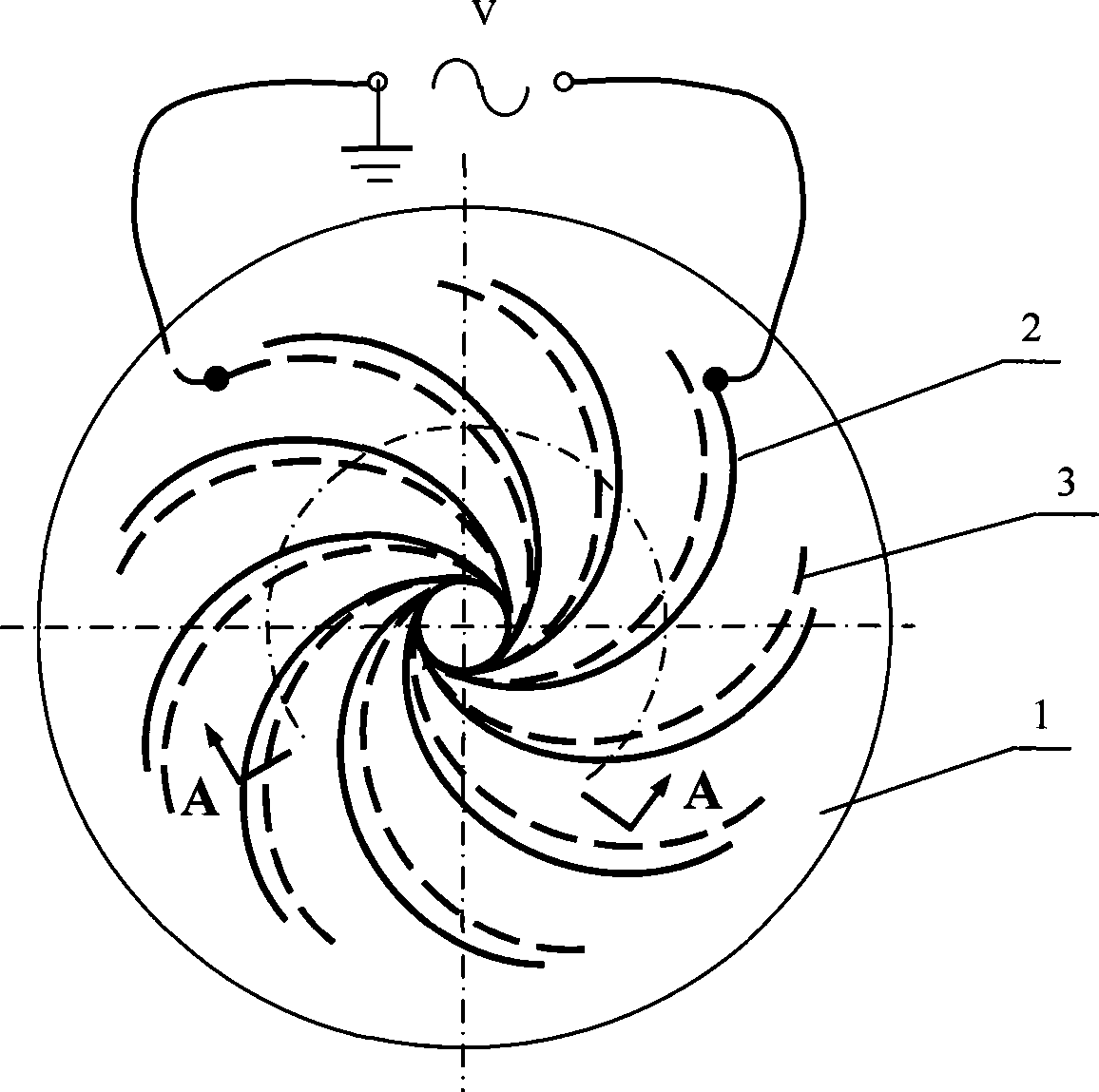
[0024] see Figure 1~4 , the present invention is provided with bottom plate 1 and high-voltage AC power supply V, and bottom plate 1 is an insulating dielectric flat plate, and 9 pairs of arc-shaped upper surface electrodes 2 and lower surface electrodes 3 are evenly covered on the upper surface and lower surface of bottom plate 1, and upper surface electrode 2 Both the electrodes 3 on the lower surface and the lower surface are arc-shaped, and are arranged radially in pairs at equal intervals along the circumferential direction. from figure 2 From above, the size of the upper surface electrode and the lower surface electrode of the same pair of arc-shaped electrodes is D 1 >D 2 , and D 2 >d 1 and D 1 —D 2 >D 2 —(d 1 +d 2 ), D 1 is the distance between adjacent upper surface electrodes 2, D 2 is the distance between the opposite sides of the upper surface electrode 2 and the lower surface electrode 3 of the same pair of arc-shaped electrodes, d 1 is the width of ...

Embodiment 2

[0031] see Figure 5 , the diameter of the bottom plate 1 is 100mm, and the thickness H≥0.5mm. Both the upper surface electrode 2 and the lower surface electrode 3 are arc segments, which are divided into three circles and evenly arranged on both sides of the bottom plate 1 . The upper surface electrodes 2 and the lower surface electrodes 3 of each ring are respectively electrically connected to a circular electrode. The upper surface electrodes 2 and the lower surface electrodes 3 on each circle are alternately arranged up and down along the circular electrodes. The inner diameter of the inner circular electrode 21 on the upper surface of the bottom plate 1 is 20mm, the inner diameter of the middle circular electrode 22 is 45mm, and the inner diameter of the outer circular electrode 23 is 70mm. The inner diameter of the inner circular electrode 31 on the lower surface of the bottom plate 1 is 10mm, the inner diameter of the middle circular electrode 32 is 35mm, and the inne...


PUM


Abstract

The invention relates to a plane rotational flow generator which belongs to a generator, in particular to a plane rotational flow generator which has simpler structure and can form rotational flows parallel to the plane or an article surface. The plane rotational flow generator is provided with a base plate and an alternating current power supply, at least four upper surface and lower surface electrodes are respectively covered on the upper surface and the lower surface of the base plate, the four upper surface and lower surface electrodes are all arc-shaped electrodes which are bent along a same direction, and the four upper surface and lower surface electrodes are pairwise and equidistantly distributed in an interlaced radiation shape along a circumference. Furthermore, the upper surface electrodes are electrically connected with each other, the lower surface electrodes are electrically connected with each other, each upper surface electrode and each lower surface electrode are respectively and electrically connected with two output ends of the alternating current power supply, and the lower surface of the base plate and the lower surface electrodes are respectively provide with electrical medium material covering layers.

Description

technical field [0001] The invention relates to a generator, in particular to a plane swirl generator. Background technique [0002] The control of boundary layer separation is an important part of flow control. There are many methods. The main guiding idea is to increase the kinetic energy of the fluid in the boundary layer and improve its ability to resist separation to inhibit separation. Jets, vortex generators, etc. are effective methods to overcome boundary layer separation. However, most jets require additional air sources, and there are many components, complex structures, difficult processing or large processing volume. However, vortex generators often require mechanical structural parts, which can negatively affect the flow when the boundary layer does not separate. In production, the requirement of blending materials is often encountered, and the existing methods often require mechanisms and power with complex structures. [0003] The invention patent applicati...

Claims


Application Information

Patent Timeline
Patent Type & Authority Applications(China)
IPC IPC(8): F15D1/00
Inventor 林麒黄印阳潘波沈锦明
Owner XIAMEN UNIV
Why Eureka
Try Eureka