Air-jet spinning device

An air-flow spinning and air-flow technology, applied in the field of air-flow spinning devices, can solve the problems of reducing yarn strength and the like

Active Publication Date: 2012-06-27
SAURER GERMANY GMBH & CO KG
View PDF2 Cites 0 Cited by
  • Summary
  • Abstract
  • Description
  • Claims
  • Application Information

AI Technical Summary

Problems solved by technology

The result is a reduction in the strength of the yarn produced

Method used


Image

  • Air-jet spinning device
  • Air-jet spinning device
  • Air-jet spinning device

Examples


Embodiment Construction

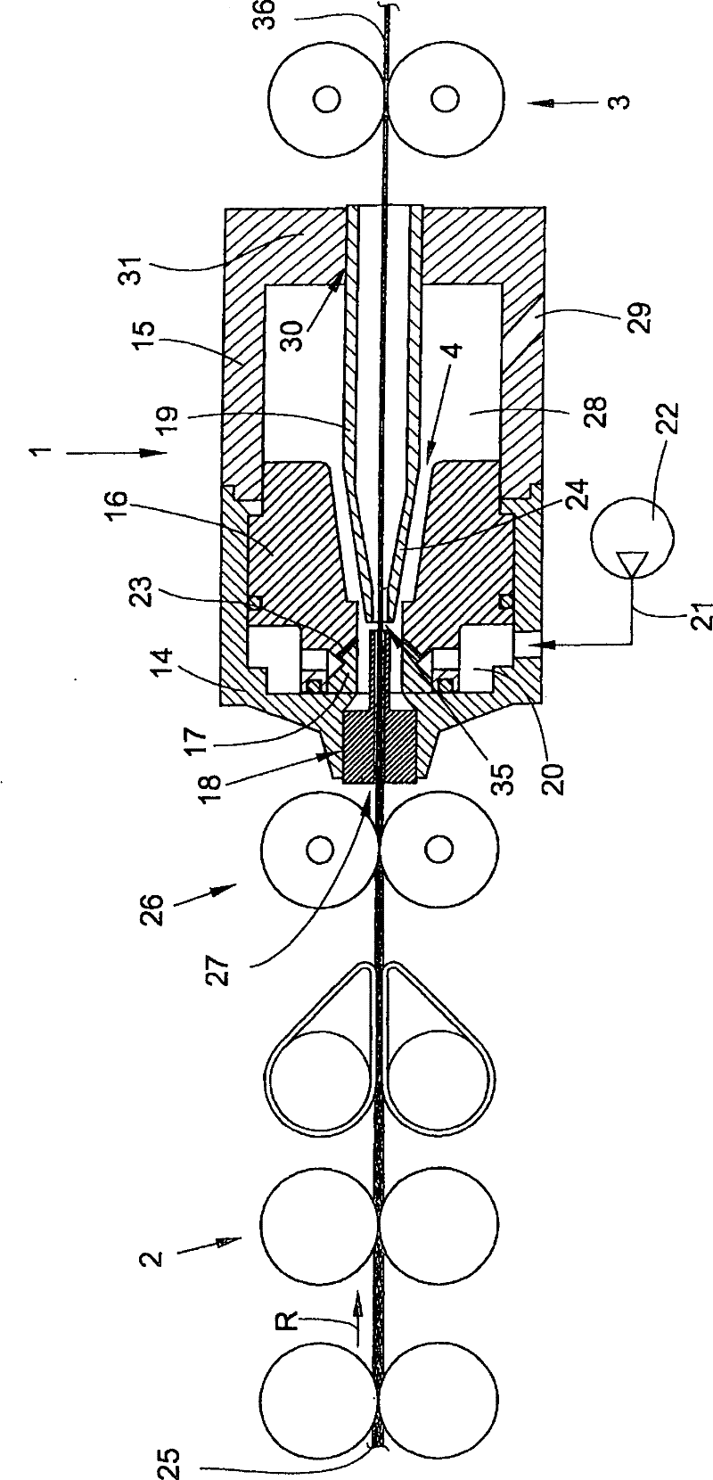
[0022] The air spinning machine has a plurality of work stations arranged next to each other and a drive unit on at least one end of the air spinning machine. as in figure 1 As schematically shown in , each station of the air spinning machine has a fiber sliver source such as a spinning barrel, an air spinning device 1 , a drafting device 2 and a yarn withdrawal mechanism 3 . The yarn 36 produced in the air spinning device 1 is wound in cross-layers by means of a yarn traversing device (not shown) to form a cross-winding drum. For this purpose, the crosswinding bobbin is held in the creel and rotated by the bobbin drive. figure 1 Only the air spinning device 1 according to the invention is shown together with the drafting device 2 connected upstream in the sliver transport direction R, and the yarn withdrawal device 3 downstream. Here, an air spinning device 1 is shown in longitudinal section, which essentially comprises two parts, an outer housing 14, 15, an extension housi...


PUM


Abstract

The invention relates to a rotor spinning device (1) for producing yarns by aid of round airflow; the rotor spinning device (1) has a housing part (16) partially surrounding a spinning nozzle (19) with a spinning cone (24) tapering against a spinning direction and an inlet (35). The housing part (16) is radially spaced from the cone (24) to form a circular cladding gap (4) between the cone (24) and the housing part (16). The housing part (16) has blow air nozzles (23) subjected to compression for producing circulating air flow. The gap is downstream to a plane, in which the air flow initiallywithdrawing from the nozzles (23) impinges the housing part (16) surrounding the spinning cone (24), where the width of the cladding gap (4) increases suddenly.

Description

technical field [0001] The invention relates to an air spinning device for producing yarn by means of a circulating air flow, comprising a shell which at least partially surrounds a hollow spinning cone with a head and an inlet, said spinning cone tapering in the opposite direction of the spinning direction, wherein said shell portion is radially spaced apart from said spinning cone so as to form an annular envelope gap between said spinning cone and said shell portion, And wherein, the housing has air jet nozzles to which compressed air can be applied for generating a circular air flow. Background technique [0002] From the same family DE 44 31 761 A1 an air spinning device is known, in which the fiber sliver drafted in the upstream drafting device is introduced into the air spinning device through a nozzle assembly and is guided via a fiber sliver guide which acts as a twist arrestor. Entrance into the hollow spinning cone in a fixed setting. The spinning cone has a tap...

Claims


Application Information

Patent Timeline
Patent Type & Authority Patents(China)
IPC IPC(8): D01H1/115D01H4/02
CPCD01H4/02D01H1/115
Inventor 赫尔穆特・福伊尔洛尚德吕・塞沙尔托马斯・魏德罗塔尔・温岑
Owner SAURER GERMANY GMBH & CO KG
Why Eureka
Try Eureka