Denture forming machine for dental use

A technology for molding devices and dentures, applied in dental prosthesis, dentistry, dentures, etc., can solve the problems of expanding size, energy consumption, installation and moving difficulties, etc., to reduce the quantity, reduce the waste of resources, and overcome the trouble of maintenance Effect

Inactive Publication Date: 2009-07-29
柳和政 +1
View PDF0 Cites 5 Cited by
  • Summary
  • Abstract
  • Description
  • Claims
  • Application Information

AI Technical Summary

Problems solved by technology

[0009] [09] The conventional technology uses too many members to achieve a desired operation, thereby consuming a large amount of energy due to the operation and expanding its size, so it is difficult to install and move the conventional device

Method used


Image

  • Denture forming machine for dental use
  • Denture forming machine for dental use
  • Denture forming machine for dental use

Examples


Embodiment Construction

[0055] [55] Hereinafter, the present invention will be described in more detail with reference to the accompanying drawings, in which exemplary embodiments thereof are shown.

[0056] [56] First embodiment

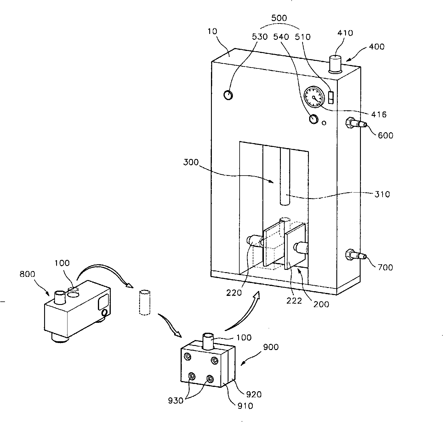
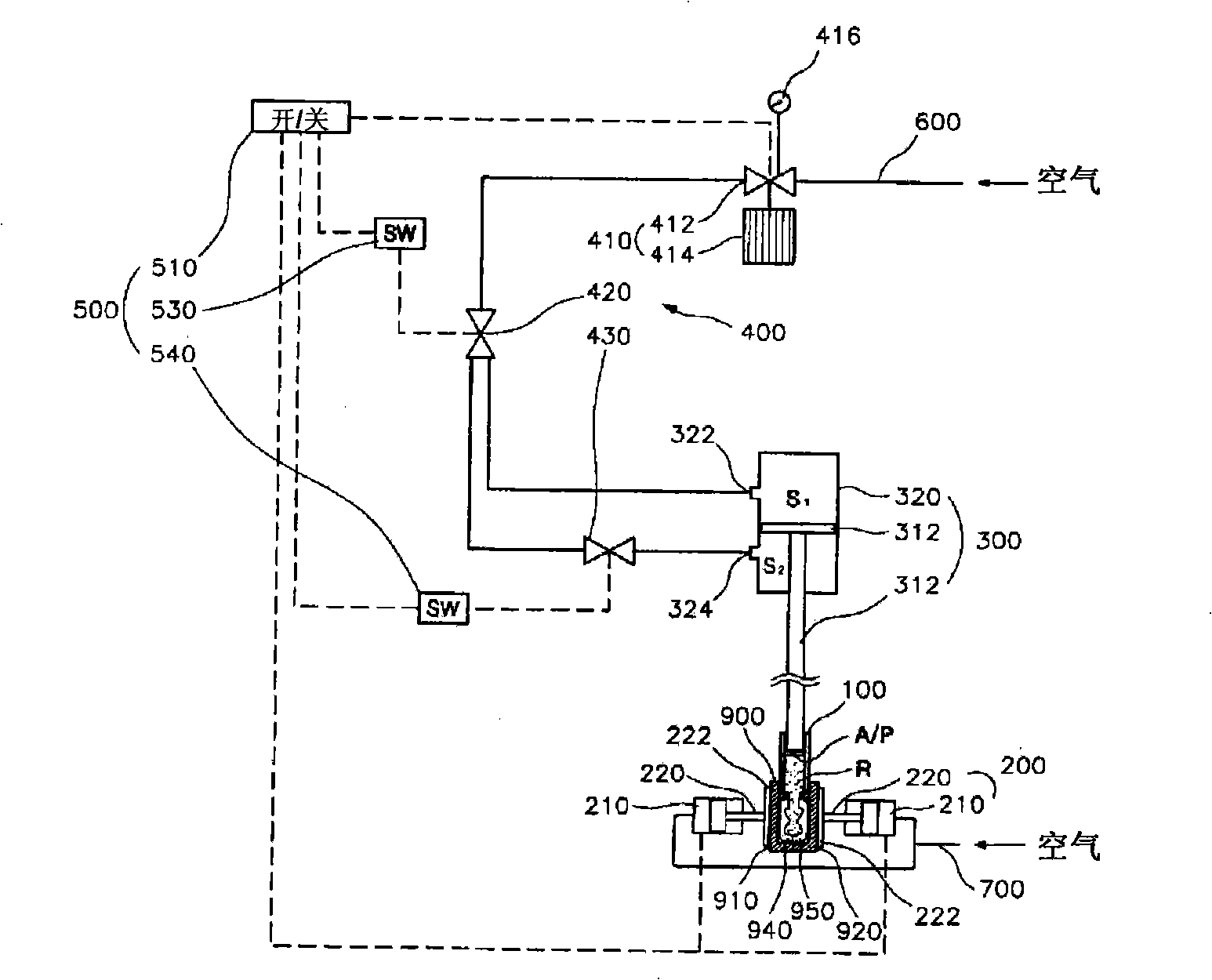
[0057] [57] figure 2 is a perspective view showing the overall external structure of a denture forming device for dental use according to the present invention, image 3 is a schematic view showing an air tube connection structure in a denture molding device for dental use according to the present invention.

[0058] [58] If figure 2 and image 3 As shown in , the denture forming device for dental use of the present invention generally includes a jig 200 , a pressing unit 300 , an air pressure adjusting unit 400 and a control unit 500 . These members 200, 300, and 500 are provided inside the casing 10, wherein the air pressure adjusting unit 400 is connected to the upper air pipe 600, and the clamp 200 is connected to the lower air pipe 700, so that the air pressure ...


PUM


Abstract

A denture forming apparatus for dental use includes clamps for protruding from and retracting to opposing sides in order to clamp or unclamp opposing side portions of the flask, thereby fixing or unfixing the flask; a pressing unit placed above the clamps to charge the resin, contained in a resin-filling pipe, into the flask under a predetermined pressure; and a control unit for controlling the operation of the clamps and controlling the pressing unit to descend at a predetermined rate of descent according to a type of the resin contained in the resin-filling pipe. The denture forming apparatus can be used irrespective of the type of resin since the speed of the pressing unit can be regulated. Accordingly, it is possible to realize an improvement over the conventional art, which can use only a designated type of resin.

Description

technical field [0001] [01] The present invention relates to a denture molding device used in dentistry, and specifically, the denture molding device may employ a structure capable of pressing molten resin at an appropriate air pressure and an appropriate descending speed to form in a flask Dentures such that they can be widely used regardless of the type of resin, and various types of dentures can be formed quickly and efficiently. Background technique [0002] [2] Generally, to form dentures, powdered resin is melted by heating, and workers manually fill the melted resin into a denture model such as a sand box at a predetermined pressure. [0003] [03] However, it is difficult to stably apply a constant pressure in such a manual operation, foam is not sufficiently discharged from the heat-melted resin, thereby increasing the occurrence rate of defects. [0004] [04] Considering these problems, a Korean utility model named "APPARATUS FOR CHARGING AND CURINGTHERMAL SYNTHETI...

Claims


Application Information

Patent Timeline
Patent Type & Authority Applications(China)
IPC IPC(8): A61C13/20
CPCA61C13/081A61C9/00A61C13/08A61C13/20
Inventor 柳和政黄寿泰
Owner 柳和政
Why Eureka
Try Eureka