Assembled battery formed by stacking a plurality of flat cells
A battery pack, flat shape technology, applied in the direction of battery pack parts, circuits, electrical components, etc., can solve the problem of not being able to accommodate the battery pack, and achieve the effects of improving the buffering effect, preventing dislocation, and promoting heat dissipation
- Summary
- Abstract
- Description
- Claims
- Application Information
AI Technical Summary
Problems solved by technology
Method used
Image
Examples
Embodiment 1
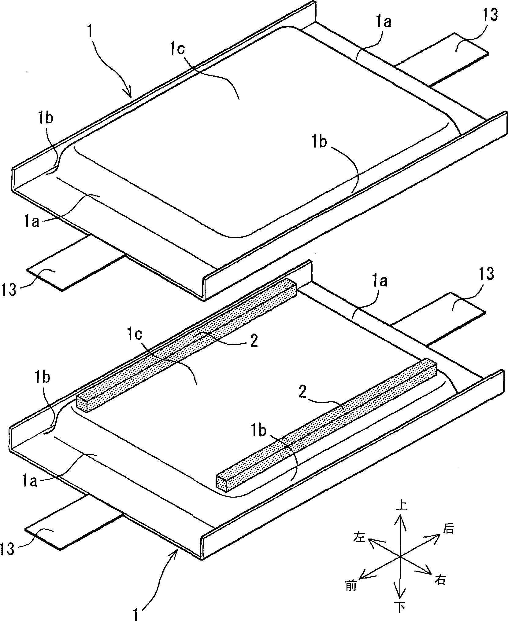
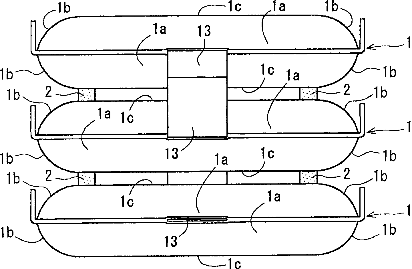
[0081] Example 1, such as figure 1 with figure 2 As shown, two rod-shaped spacers 2 are arranged between opposing flat surfaces 1 c of adjacent non-aqueous electrolyte secondary batteries 1 stacked up and down (an embodiment of the second aspect of the present invention). These spacers 2 are square pillars with approximately the same length as the front and rear distances of the flat surfaces 1c of the non-aqueous electrolyte secondary battery 1, and are arranged at the left and right ends between the opposing flat surfaces 1c. Each spacer 2 may be formed of a hard resin molded product or the like, but is preferably formed of an elastic body such as rubber. In addition, each spacer 2 is preferably adhered to the flat surface 1c using a double-sided adhesive tape, an adhesive, or the like, so that the positions are not easily shifted.
[0082] In addition, in the non-aqueous electrolyte secondary battery 1 shown in Example 1, the left and right widths of the battery pack ar...
Embodiment 2
[0089] Example 2, such as Figure 4 with Figure 5 As shown in FIG. 1 , a case is shown in which a frame-shaped spacer 4 is disposed between opposing side end portions 1 b of adjacent non-aqueous electrolyte secondary batteries 1 stacked up and down (an embodiment of the third aspect of the present invention). One frame-shaped spacer 4 is used for each of the right side end portion 1b and the left side end portion 1b. These spacers 4 are frame bodies made of resin thin plates manufactured by resin molding, and are composed of an upper support portion 4a and a lower support portion 4b. The upper support portion 4a is a portion where a resin sheet is bent into a concave shape to support the downward one side end portion 1b and the front and rear end portions 1b of the nonaqueous electrolyte secondary battery 1 adjacent above. The lower support portion 4b is a portion where a resin sheet is bent into a concave shape to support the upward one side end portion 1b and the front an...
Embodiment 3
[0094] Example 3, such as Image 6 with Figure 7 As shown, the spacer 5 is arranged between the opposing flat surfaces 1c and the side ends 1b (both left and right) of adjacent non-aqueous electrolyte secondary batteries 1 stacked up and down (fourth aspect of the present invention). aspect example). The spacer 5 has a plate shape manufactured by resin molding, and has battery support portions 5a formed at both left and right end portions. The battery support portion 5a is a portion where both end portions of the spacer 5 protrude in the vertical direction.
[0095] The battery support portion 5 a is a portion bent and formed in a concave shape to support the side end portions 1 b of the non-aqueous electrolyte secondary batteries 1 adjacent up and down. In addition, these battery support portions 5a are provided with substantially triangular triangular holes 5b penetrating in the front-rear direction. In addition, in the non-aqueous electrolyte secondary battery 1 shown ...
PUM
 Abstract
Description
Claims
Application Information
 - R&D
- Intellectual Property
- Life Sciences
- Materials
- Tech Scout
- Unparalleled Data Quality
- Higher Quality Content
- 60% Fewer Hallucinations
Browse by: Latest US Patents, China's latest patents, Technical Efficacy Thesaurus, Application Domain, Technology Topic, Popular Technical Reports.
© 2025 PatSnap. All rights reserved.Legal|Privacy policy|Modern Slavery Act Transparency Statement|Sitemap|About US| Contact US: help@patsnap.com


