Ambient temperature thermal energy and constant pressure cryogenic engine

A surrounding environment and engine technology, applied in variable displacement engines, machine/engines, reciprocating piston engines, etc., can solve problems such as harmful output of machines

Inactive Publication Date: 2009-07-22
MDI MOTOR DEV INT SA
View PDF9 Cites 15 Cited by
  • Summary
  • Abstract
  • Description
  • Claims
  • Application Information

AI Technical Summary

Problems solved by technology

[0013] In these pressure reducing devices, the filling of the chamber always signifies a release of pressure, which is detrimental to the usual output of the machine

Method used


Image

  • Ambient temperature thermal energy and constant pressure cryogenic engine
  • Ambient temperature thermal energy and constant pressure cryogenic engine
  • Ambient temperature thermal energy and constant pressure cryogenic engine

Examples


Embodiment Construction

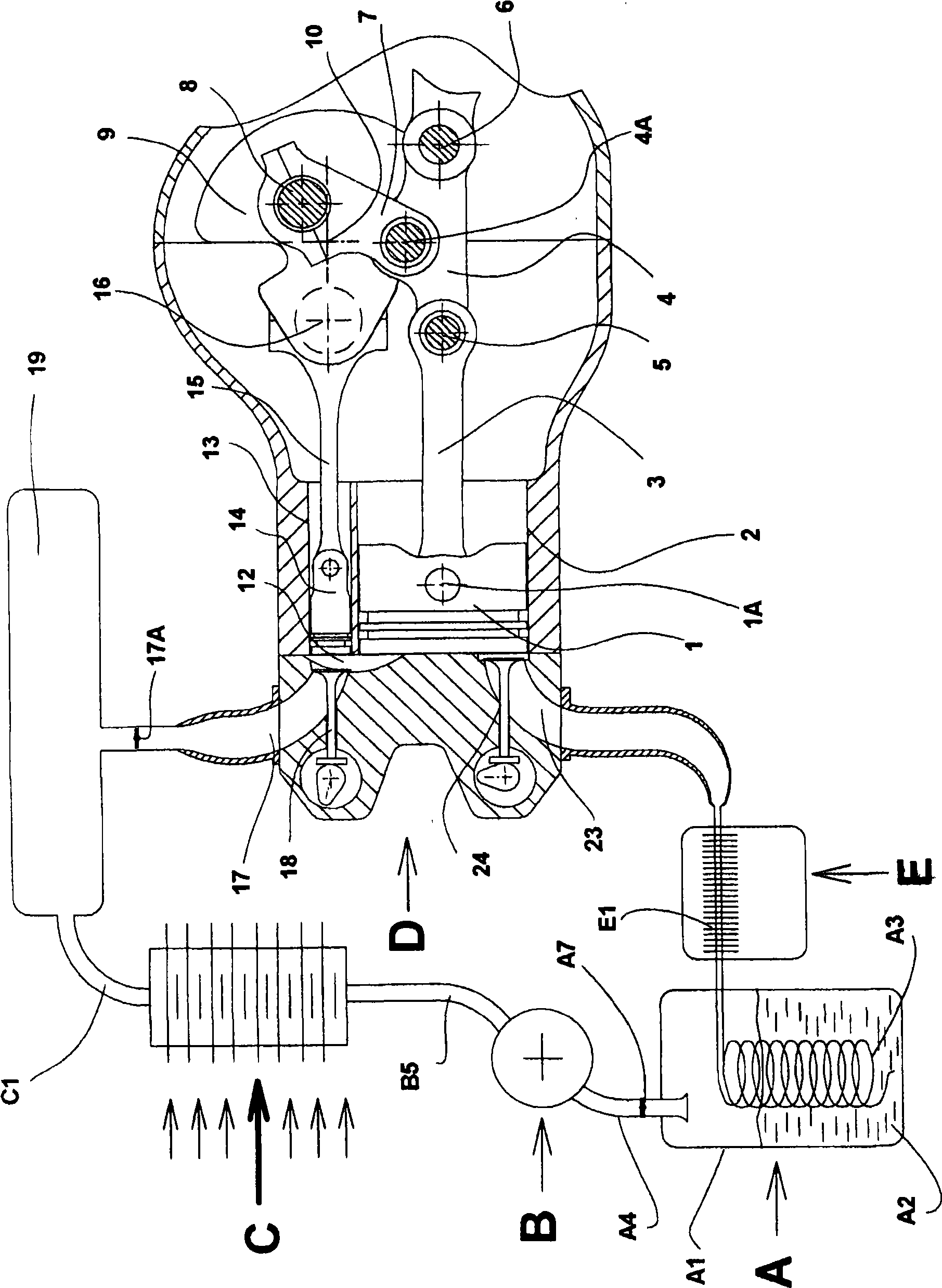
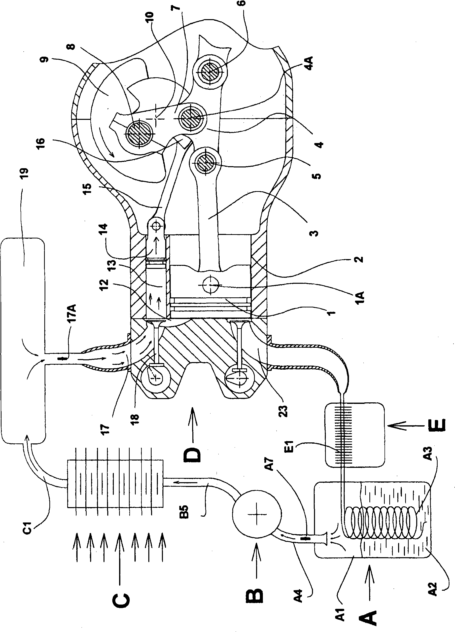
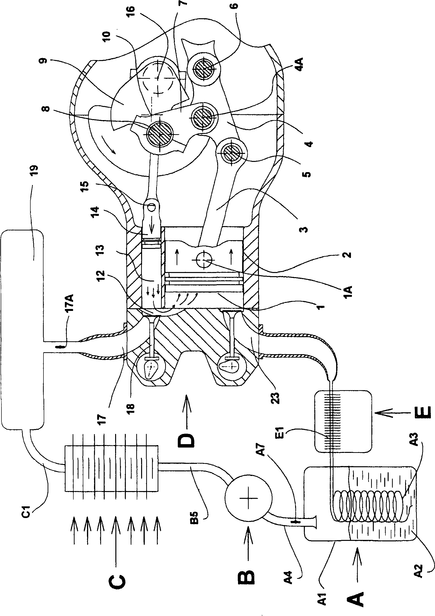
[0157] figure 1 It is a cross-sectional structural diagram of a thermal energy cryogenic engine at ambient temperature according to the present invention, which includes five main components: storage A for cryogenic fluid in liquid phase, very low temperature compressor B, gas / ambient air exchanger C , a work-doing volume release device D with an active chamber and a cryogenic machine E for cooling before liquefaction, in which can be seen an accumulator A1 in which a cryogenic fluid A2 in liquid phase is stored, which accumulator A1 comprises There is heat exchanger A3 for liquefaction and evaporation. The accumulator is connected to the inlet of the cryogenic compressor B through the pipe A4, the outlet of the cryogenic compressor B is connected to the cryogenic fluid / ambient air exchanger C through the pipe B5, and the cryogenic fluid / ambient air exchanger C It is itself connected via line C1 to a constant pressure expansion tank 19 which is itself connected to the inlet 1...


PUM


Abstract

The invention relates to an ambient temperature thermal energy cryogenic engine with constant pressure with continuous ''cold'' combustion at constant pressure and with an active chamber operating with a cryogenic fluid (A2) stored in its liquid phase, and used as a work gas in its gaseous phase and operating in a closed cycle with return to its liquid phase. The initially liquid cryogenic fluid is vaporized in the gaseous phase at very low temperatures and supplies the inlet (A4) of a gas compression device (B), which then discharges this compressed work gas, still at low temperature, and through a heat exchanger with the ambient temperature (C), into a work tank or external expansion chamber (19) fitted or not fitted with a heating device, where its temperature and its volume will considerably increase in order to then be preferably let into a relief device (D) providing work and for example comprising an active chamber according to international patent application WO 2005 / 049968. Application to land vehicles, motor vehicles, buses, motorcycles, boats, aircraft, standby generators, cogeneration sets, stationary engines.

Description

technical field [0001] This invention relates to engines. [0002] More particularly, the present invention relates to engines, operating especially with cryogenic fluids, using means for controlling the stroke of the pistons to have the effect of stopping the pistons at their top dead center for a period of time and spinning the engine, which engines also use A variable volume active chamber that does work, an integrated (or separate) compression device, and a device for recovering heat energy at ambient temperature. Background technique [0003] The inventors have filed numerous patents and patent applications concerning drives and their devices, using gases, especially compressed air, for completely clean operation in urban and suburban areas: [0004] WO 96 / 27737-WO 97 / 00655-WO 97 / 39232-WO 97 / 48884- [0005] WO 98 / 12062-WO 98 / 15440-WO 98 / 32963-WO 99 / 37885- [0006] WO 01 / 69080-WO 03 / 036088 [0007] In order to implement these inventions, a method and apparatus have a...

Claims


Application Information

Patent Timeline
Patent Type & Authority Applications(China)
IPC IPC(8): F01B17/02F02G1/04F01K25/08
CPCF01K25/10F01B17/025F02G1/04F01K15/00F01B17/02F01K25/08
Inventor G·内格尔C·内格尔
Owner MDI MOTOR DEV INT SA
Why Eureka
Try Eureka