Electric razor

An electric and motor technology, applied in metal processing, etc., can solve the problem of heavy head weight, achieve balanced weight distribution, reduce weight, and simplify setup and installation

Active Publication Date: 2013-10-16
BRAUN AG
View PDF2 Cites 2 Cited by
  • Summary
  • Abstract
  • Description
  • Claims
  • Application Information

AI Technical Summary

Problems solved by technology

Since the entire electric motor with its two rotors is arranged in the trimming head, on the one hand, all energy and control circuits must be introduced into this vibrating component, and it must also be pointed out that this shaving device is obviously a head too much weight

Method used


Image

  • Electric razor
  • Electric razor
  • Electric razor

Examples


Embodiment Construction

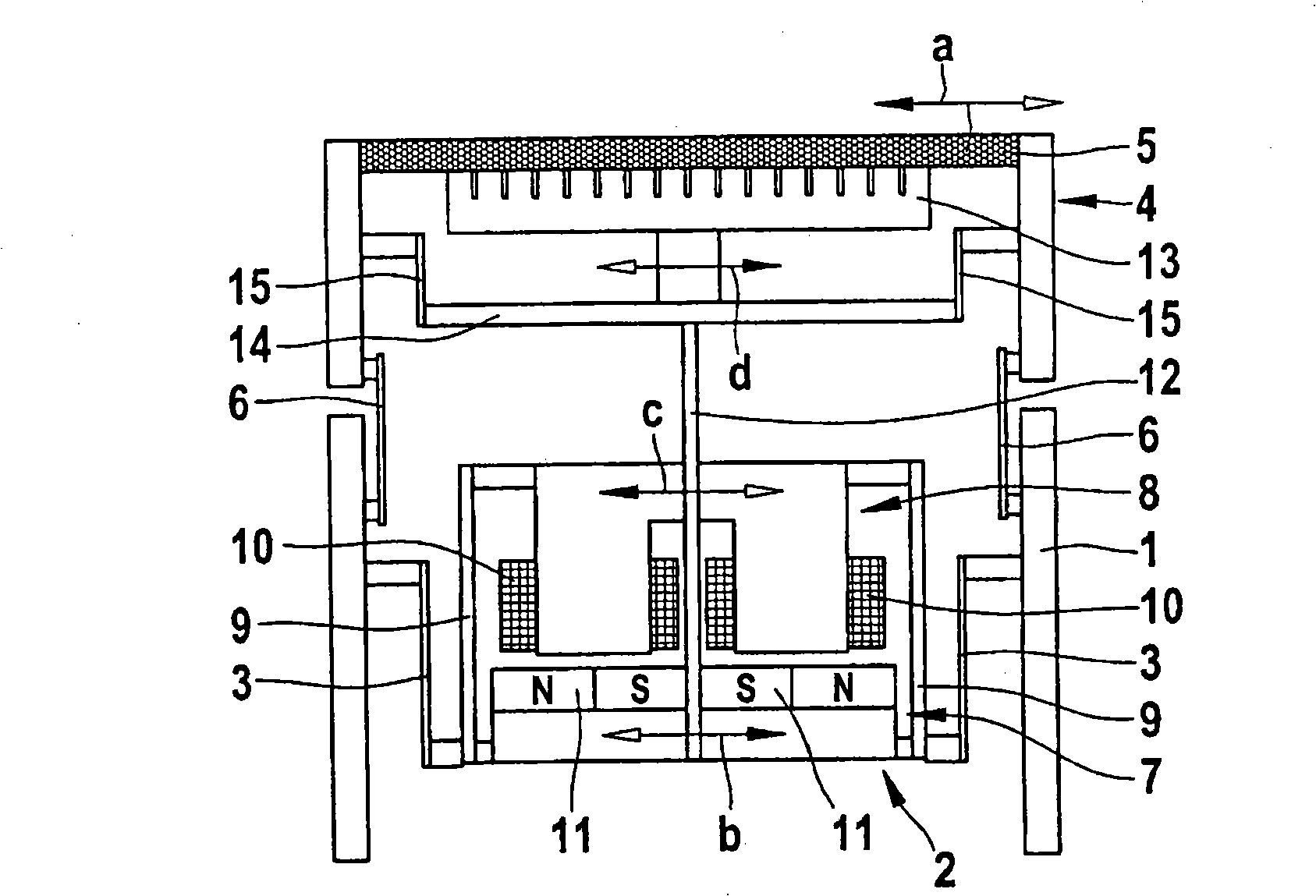
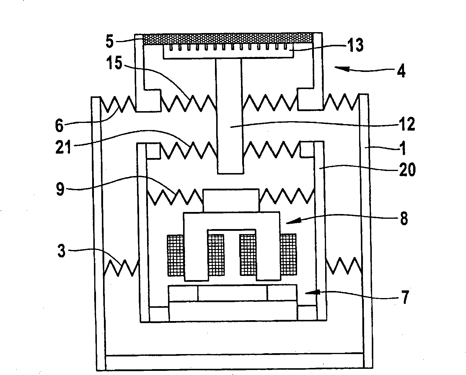
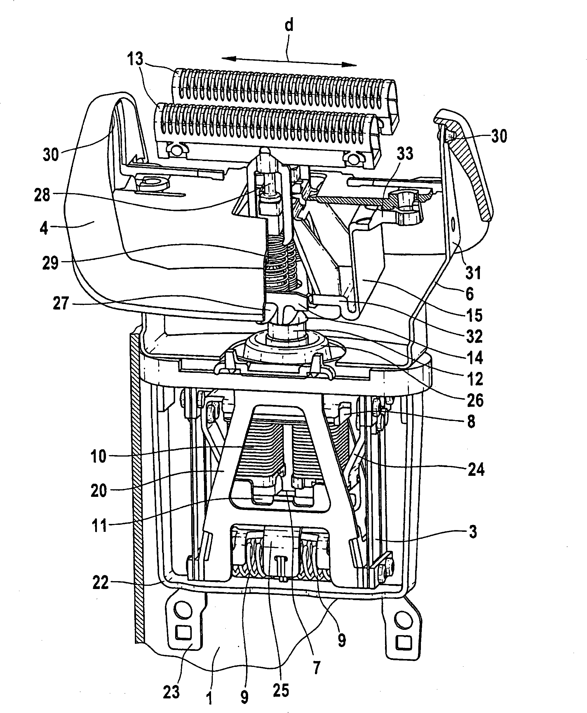
[0017] exist figure 1 The shaving apparatus schematically shown in has a housing 1 held in the hand of the user, which houses the electric motor 2 as well as the energy supply in the form of accumulators and / or power supply parts, not shown in its view, and the complete motor control , switch, etc. The electric motor 2 is elastically supported in the housing 1 by means of a motor suspension 3 designed as a plurality of leaf springs in order to prevent the transmission of motor vibrations to the housing 1 .

[0018] The trimming head 4 carries at least one trimming sheet 5 , which is a first trimming element, and the trimming head 4 is connected to the housing 1 in a vibrating manner by means of two trimming head carriers 6 . The leaf-spring-shaped trimming head carrier 6 permits lateral vibrations of the trimming head 4 and thus of the trimming blade 5 in the plane of the drawing, as indicated by the double arrow a.

[0019] The electric motor 2 is formed from a first rotor ...


PUM


Abstract

An electric shaving apparatus including a housing and a shaving head. The shaving head is coupled to the housing by at least one first elastic element and includes at least one first shaving element. The electric shaving apparatus includes in addition an electric motor for generating an oscillatory motion of the shaving head and an oscillatory motion differing therefrom of at least one second shaving element. The electric motor includes two drive components of which a first drive component is adapted to be driven to oscillate relative to a second drive component. One of the drive components is connected to the second shaving element. The second shaving element or a drive part connected thereto is equipped with an elastic connection to the shaving head.

Description

technical field [0001] The invention relates to an electric shaver according to the preamble of patent claim 1 . Background technique [0002] Such a shaving device is known from DE-A 103 30 978 . There is disclosed an electric shaver having a linear motor with two rotors. The trimming head of this shaver is vibratingly connected with the housing through a leaf spring, and the linear motor is suspended inside the trimming head. At least one rotor is connected to at least one trimming element designed as a lower cutter in order to cut off hair in conjunction with an associated further trimming element configured as a trimming blade. In addition, counter-rotating oscillations of the lower cutter and trimming lamellae are provided. Since the entire electric motor with its two rotors is arranged in the trimmer head, on the one hand, all energy and control circuits must be introduced into this vibrating component. The weight is too large. This is disadvantageous in terms of ...

Claims


Application Information

Patent Timeline
Patent Type & Authority Patents(China)
IPC IPC(8): B26B19/28
CPCB26B19/282B26B19/28B26B19/288
Inventor 伯恩哈德·克劳斯乌韦·舍贝尔德特勒夫·格莱希托马斯·韦尔施泰格托比亚斯·施瓦茨
Owner BRAUN AG
Why Eureka
Try Eureka