
Method for measuring frequency response function of vibrating structure in large noise environment

A frequency response function and structural frequency technology, which is applied in the testing of machines/structural components, measuring devices, vibration testing, etc., can solve the problems of unsatisfactory denoising effect and large amount of calculation, achieve ideal denoising effect and improve measurement Accuracy, the effect of achieving signal-to-noise separation

Inactive Publication Date: 2010-12-08
NORTHWESTERN POLYTECHNICAL UNIV
View PDF0 Cites 0 Cited by
  • Summary
  • Abstract
  • Description
  • Claims
  • Application Information

AI Technical Summary

Problems solved by technology

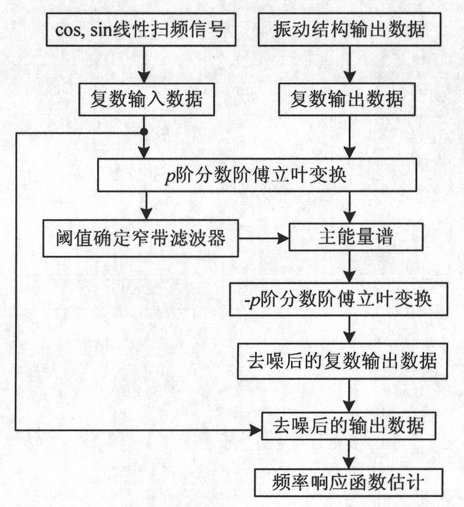
[0006] In order to avoid the deficiencies of the prior art, the present invention proposes a method for measuring the frequency response function of a vibrating structure in a noisy environment, which can overcome the disadvantages of the existing method that the denoising effect is not ideal and the amount of calculation is too large

Method used

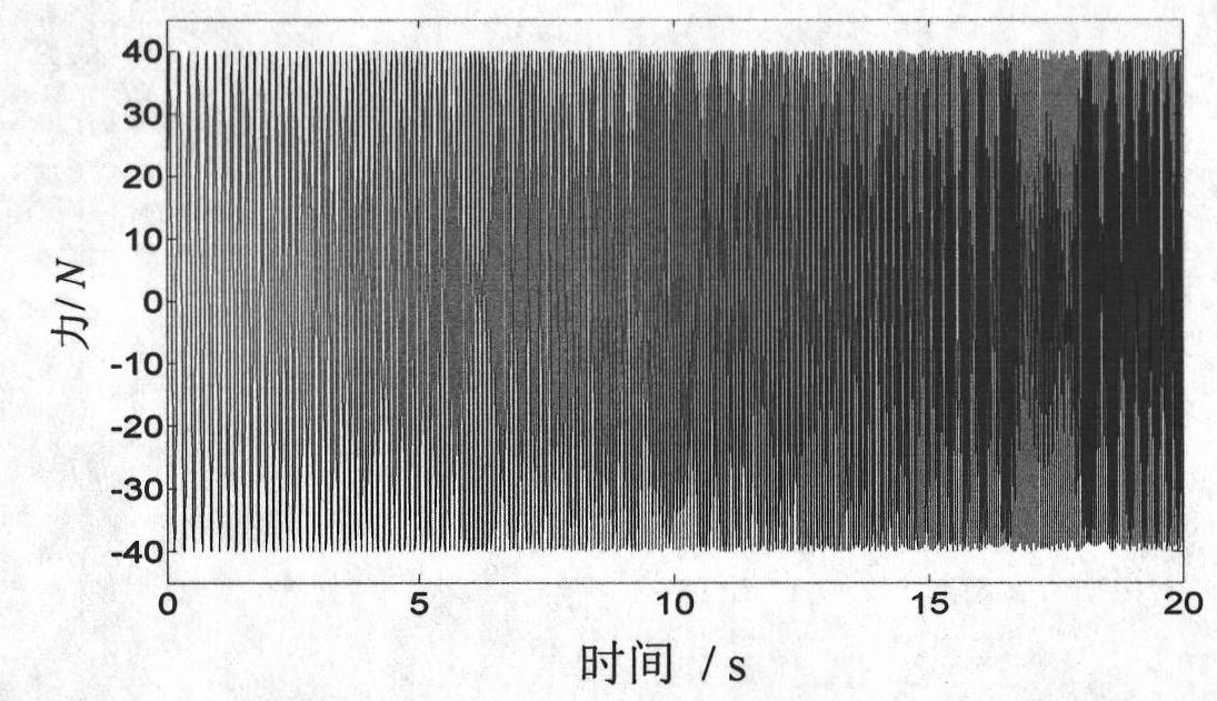
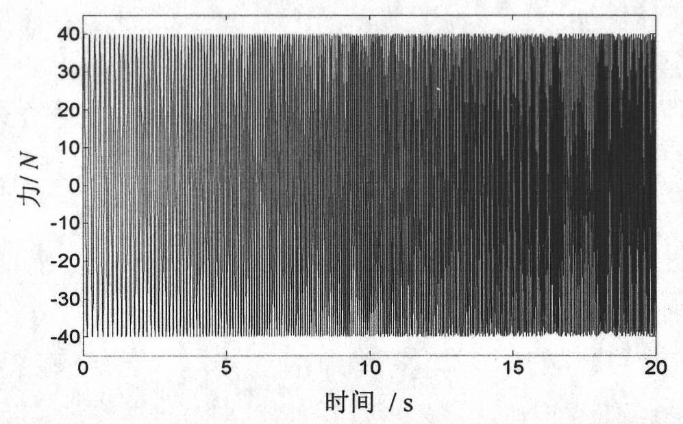

Image

  • Method for measuring frequency response function of vibrating structure in large noise environment
  • Method for measuring frequency response function of vibrating structure in large noise environment
  • Method for measuring frequency response function of vibrating structure in large noise environment

Examples


Embodiment Construction

[0039] Now in conjunction with embodiment, accompanying drawing, the present invention will be further described:

[0040] In order to better illustrate the content of the embodiments of the present invention, the fractional Fourier transform is briefly introduced below first. Fractional Fourier transform is a generalized form of Fourier transform. It can be interpreted as rotating the coordinate axis of the signal counterclockwise around the origin on the time-frequency plane. It is a new time-frequency analysis tool.

[0041] The p-order fractional Fourier transform of a signal x(t) is defined as:

[0042] X p ( u ) = F p { x ( t ) } = ∫ - ∞ + ∞ x ( t ...


PUM


Abstract

The invention relates to a method for measuring frequency response function of a vibration structure in loud-noise environment, comprising the following steps: a linear swept-frequency signal is adopted as an excitation signal and acceleration response signals of the structure vibration is filtered in a fractional order Fourier domain by fractional order Fourier transformation, so that effect of noise in non-stationary process can be lessened, and measuring accuracy of the frequency response function is improved. Simultaneously, in the method, two groups of experiment signal data are expressed as one group of plural experiment signal data so as to avoid effect of superposition of two signal components, and only one-time filtering is needed to finish noise removal treatment of the two groups of the experiment signal data so as to improve noise removal effect and operating speed.

Description

technical field [0001] The invention relates to a method for measuring the frequency response function of a vibrating structure in a large noise environment, belonging to the field of experimental modal analysis. Background technique [0002] The modal experimental analysis technology refers to obtaining the vibration response signal of the structure by applying artificial excitation to the vibrating structure, and then relying on the experimental data to extract the modal parameters of the structure. Among them, the use of experimental data to measure the frequency response function of the vibrating structure is an important part of the experiment. However, in some modal experiments, the vibrating structure is inevitably affected by natural excitation in addition to artificial excitation. For example, an airplane in flight is also excited by atmospheric turbulence when performing modal experiments, and an ocean platform structure is also excited by waves when performing mo...

Claims


Application Information

Patent Timeline
Patent Type & Authority Patents(China)
IPC IPC(8): G01M7/02G06F17/14
Inventor 唐炜史忠科陈杰罗志勇
Owner NORTHWESTERN POLYTECHNICAL UNIV
Learn More