High-torsion plate welding screw cap

A flat plate welding, high torsion technology, applied in the direction of nuts, connecting components, threaded fasteners, etc., can solve the problem that the bolts cannot be locked tightly, and achieve the effect of not being easy to face and improving the torsional strength

Inactive Publication Date: 2009-07-15
恒耀工业股份有限公司
View PDF0 Cites 6 Cited by
  • Summary
  • Abstract
  • Description
  • Claims
  • Application Information

AI Technical Summary

Problems solved by technology

However, because the upper clamping part 122 and the lower clamping part 123 only have the function of clamping against the welded plate body 11 up and down, and there is no other anti-torsion structural design, so when the flat welding nut 1 is used, the nut body 12 often occurs. Unable to bear the torsion force applied by the bolt (not shown in the figure) corresponding to the screw, the situation of relative rotation of the welded plate body 11 occurs, so that the bolt cannot be tightened and locked

Method used


Image

  • High-torsion plate welding screw cap
  • High-torsion plate welding screw cap
  • High-torsion plate welding screw cap

Examples


Embodiment Construction

[0011] Below in conjunction with accompanying drawing and embodiment the present invention is described in detail:

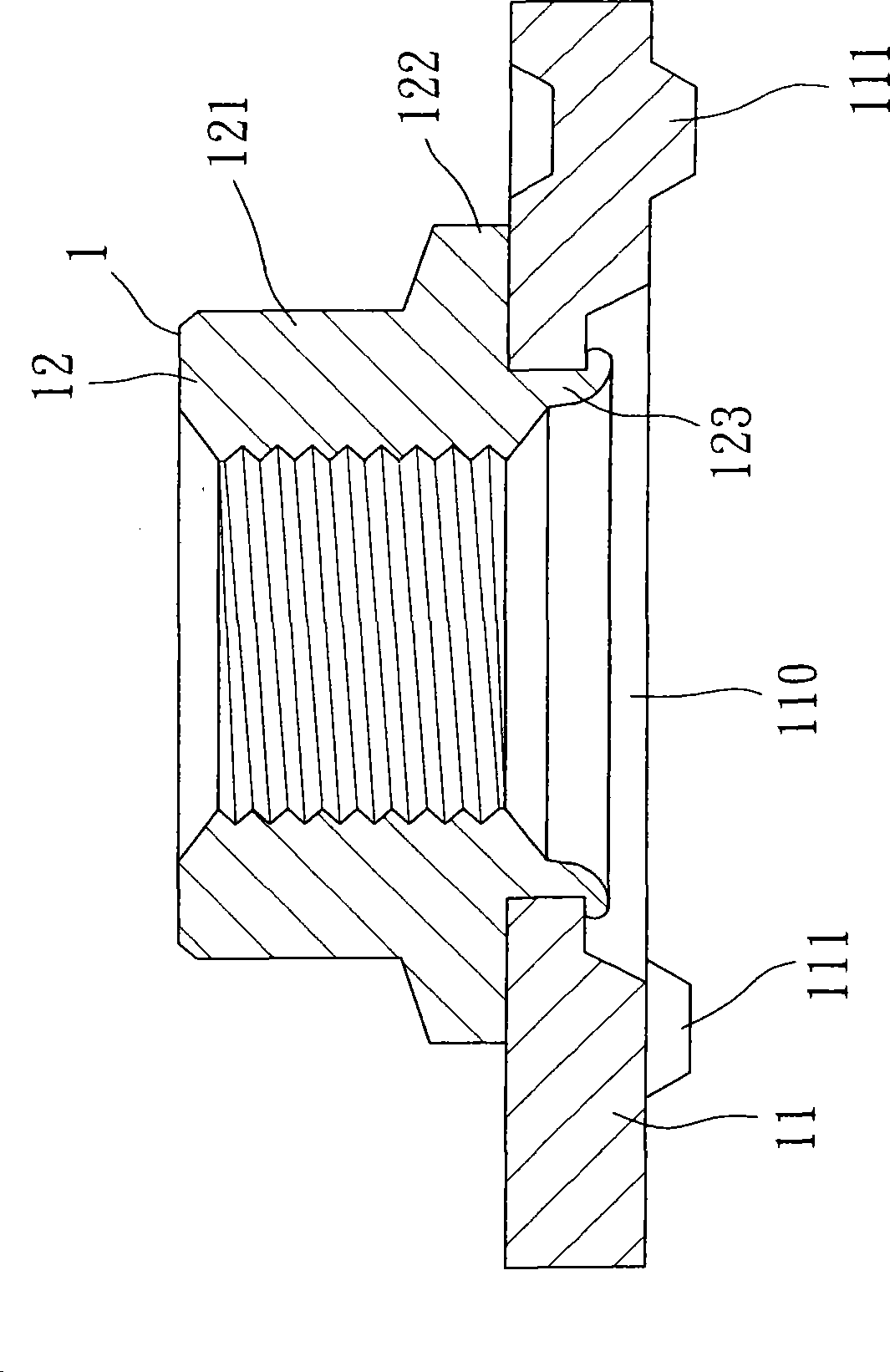
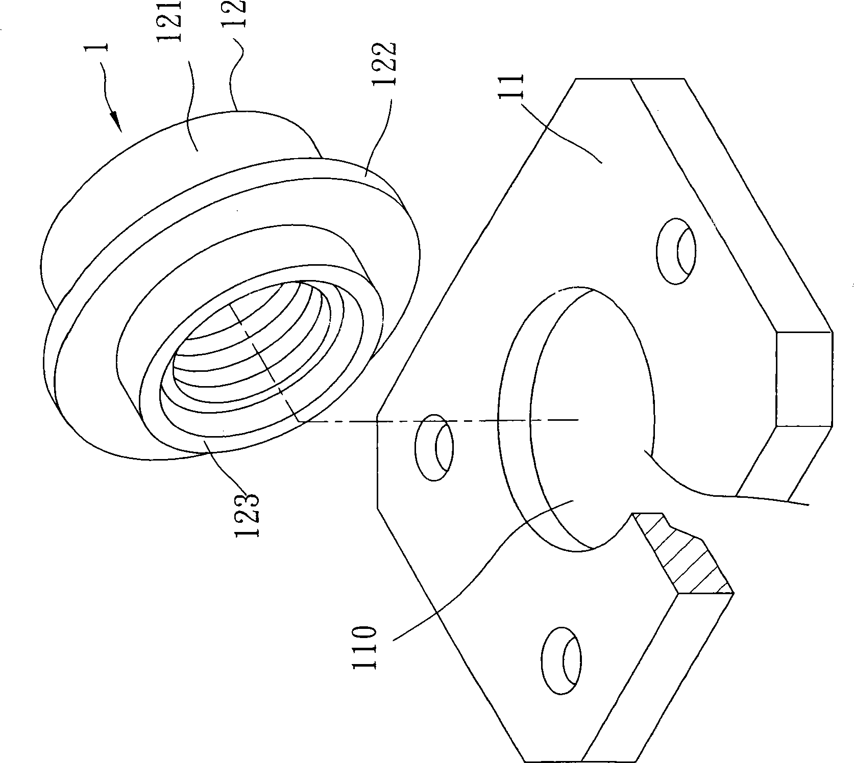
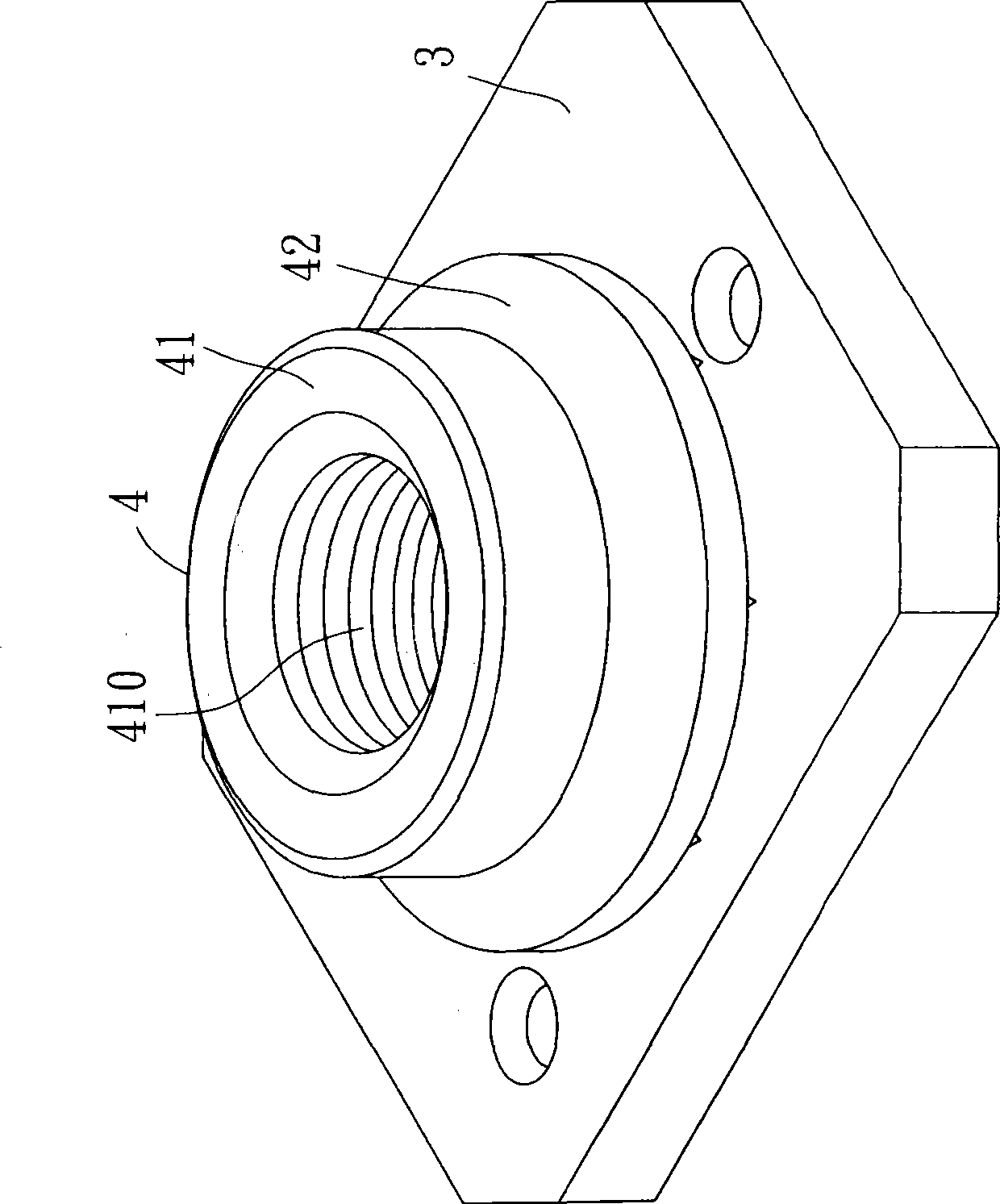
[0012] Such as Figure 3-5 As shown, the embodiment of the high-torque flat welding nut of the present invention includes a welding plate body 3 and a nut body 4 fixedly mounted on the welding plate body 3 .

[0013] The welding plate body 3 has a circular installation hole 30 penetrating through its top and bottom surfaces, and three welding protrusions 31 protruding from its bottom surface at intervals and symmetrically. The mounting hole 30 has a large aperture portion 301 , a shoulder portion 302 , and a small aperture portion 303 with a smaller diameter than the large aperture portion 301 from bottom to top.

[0014] The nut body 4 includes a nut portion 41 with thread 410 inside, an annular upper clamping portion 42 protruding radially from the bottom edge of the outer peripheral surface of the nut portion 41 , and a The annular lower clamping portion 43...


PUM


Abstract

The invention discloses a high-torque force plate welding nut which comprises a welding plate body and a nut body. The nut body comprises a nut part resisting against the top surface of the welding plate body, an annular upper clipping part which is arranged at the outer circle surface of the nut part in a protrudent way and resists against the top surface of the welding plate body, and an annular lower clipping part which penetrates downwards through the welding plate body from the nut part coaxially and is rolled to limit the position upwards to resist against the welding plate body. The upper clipping part is provided with a plurality of upper positioning ribs which are forced downwards to resist against the welding plate body. The lower clipping part is provided with a plurality of lower positioning ribs which are forced upwards to resist against the welding plate body. The design of the structure that the upper positioning ribs at the upper clipping part and the lower positioning ribs at the lower clipping part clip and fix the welding plate body oppositely can improve the anti-torsional strength between the nut body and the welding plate body greatly and ensure that the nut body does not rotate towards the welding plate body easily.

Description

technical field [0001] The invention relates to a nut, in particular to a flat welding nut. Background technique [0002] Such as figure 1 , 2 As shown, a general flat welding nut 1 roughly includes a welding plate body 11 and a nut body 12 installed and fixed on the welding plate body 11 . The welding plate body 11 has a perforation 110 through its top and bottom surfaces, and a plurality of welding points 111 protruding from its bottom surface. The nut body 12 has a nut portion 121 against the top surface of the welding plate body 11, An upper clamping portion 122 protruding radially from the outer peripheral surface of the nut portion 121 and leaning against the top surface of the welded plate body 11, and an upper clamping portion 122 protruding downward from the nut portion 121 through the through hole 110 and reaching the upper limit. The nut body 12 is installed and fixed on the welded plate body 11 mainly through the way that the upper clamped portion 122 and the ...

Claims


Application Information

Patent Timeline
IPC IPC(8): F16B37/06
Inventor 吴荣彬
Owner 恒耀工业股份有限公司
Why Eureka
Try Eureka